AC , DC, and Transients ! #SEELab3
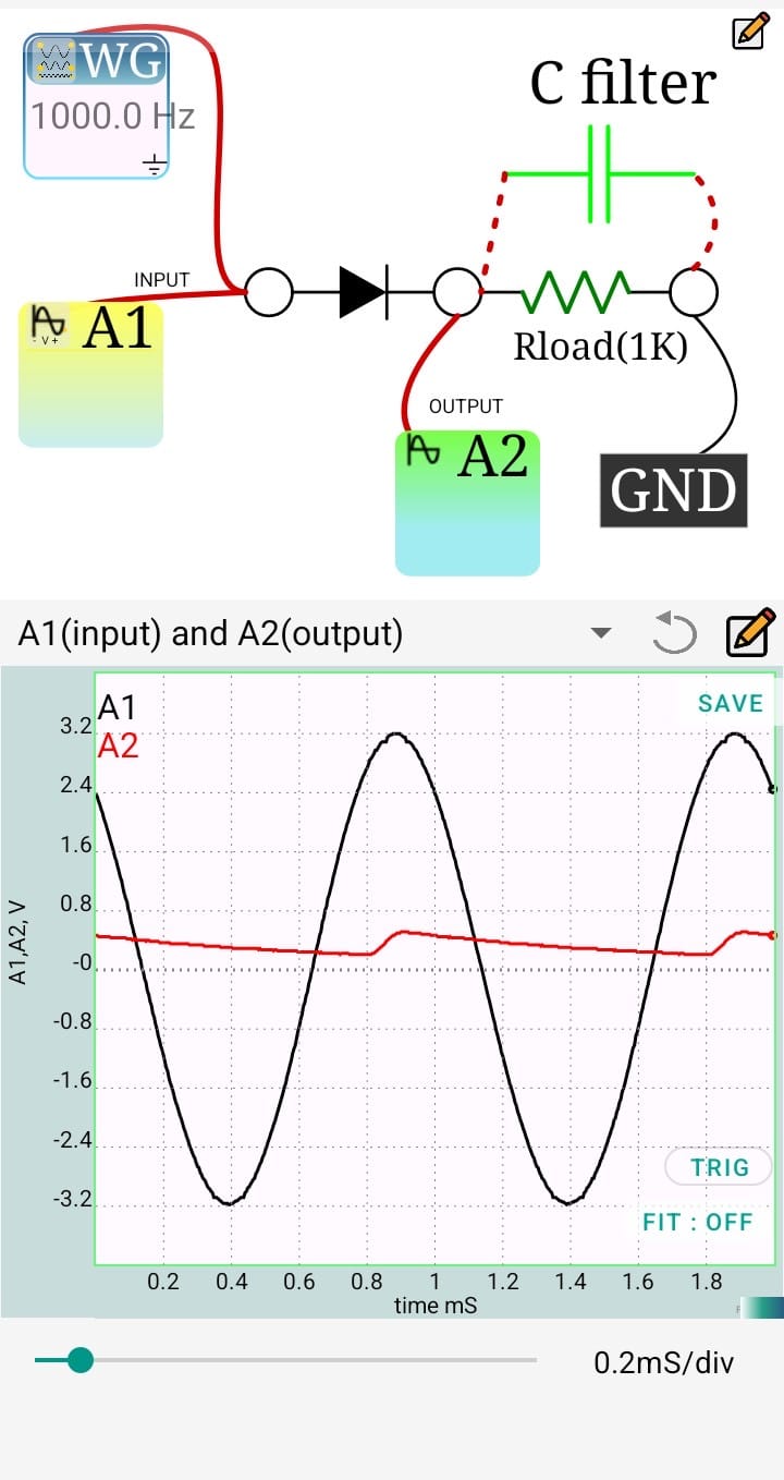
1:HALF WAVE RECTIFIER WITH FILTER
The Half Wave Rectifier experiment demonstrates how a single PN junction diode converts an alternating current (AC) signal into a pulsating direct current (DC) by allowing only one half-cycle of the input waveform to pass. Using ExpEYES, the AC input is supplied through the waveform generator (WG), while oscilloscope channels A1 and A2 are used to observe the input and rectified output waveforms, respectively. The experiment helps in understanding the rectification process, diode forward voltage drop, and the effect of adding a filter capacitor to reduce ripple and obtain a smoother DC output.
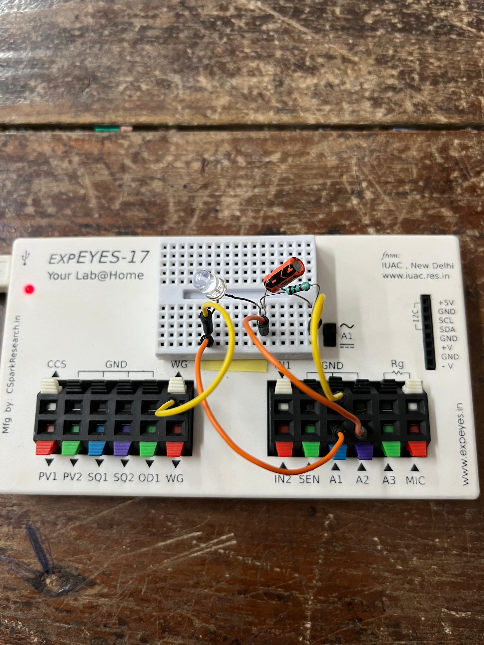
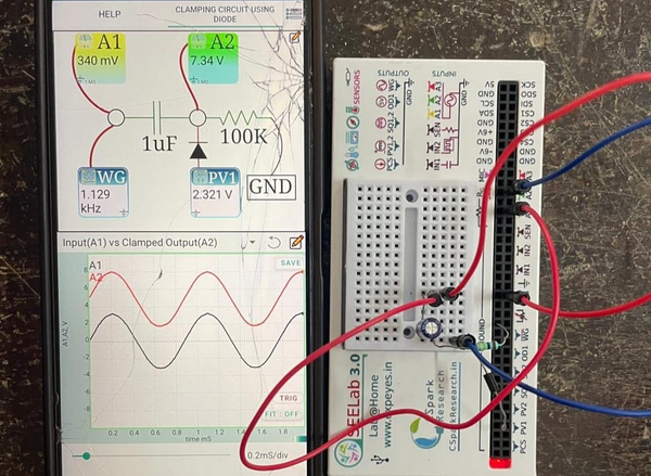
2:CLAMPING CIRCUIT USING DIODE
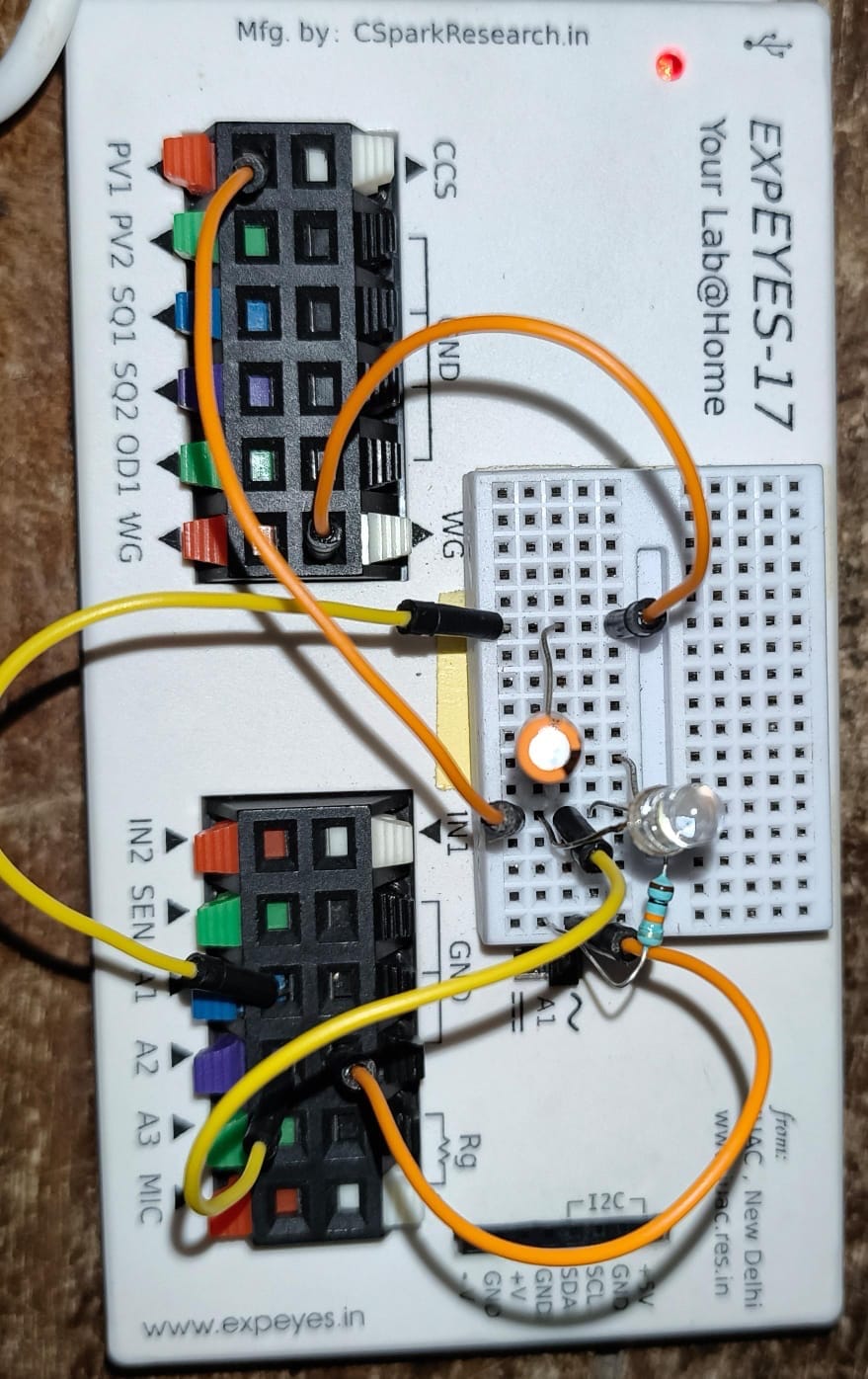
The Clamping Circuit experiment demonstrates how a diode and capacitor can shift the DC level of an AC waveform without changing its shape or peak-to-peak amplitude. Using ExpEYES, the waveform generator (WG) provides the AC input signal, while oscilloscope channels A1 and A2 are used to observe the input and clamped output waveforms, respectively. Depending on the orientation of the diode, the circuit functions as either a positive or negative clamper, effectively shifting the waveform above or below the zero-voltage reference. This experiment helps in understanding DC level shifting and the role of the diode-capacitor combination in signal conditioning.
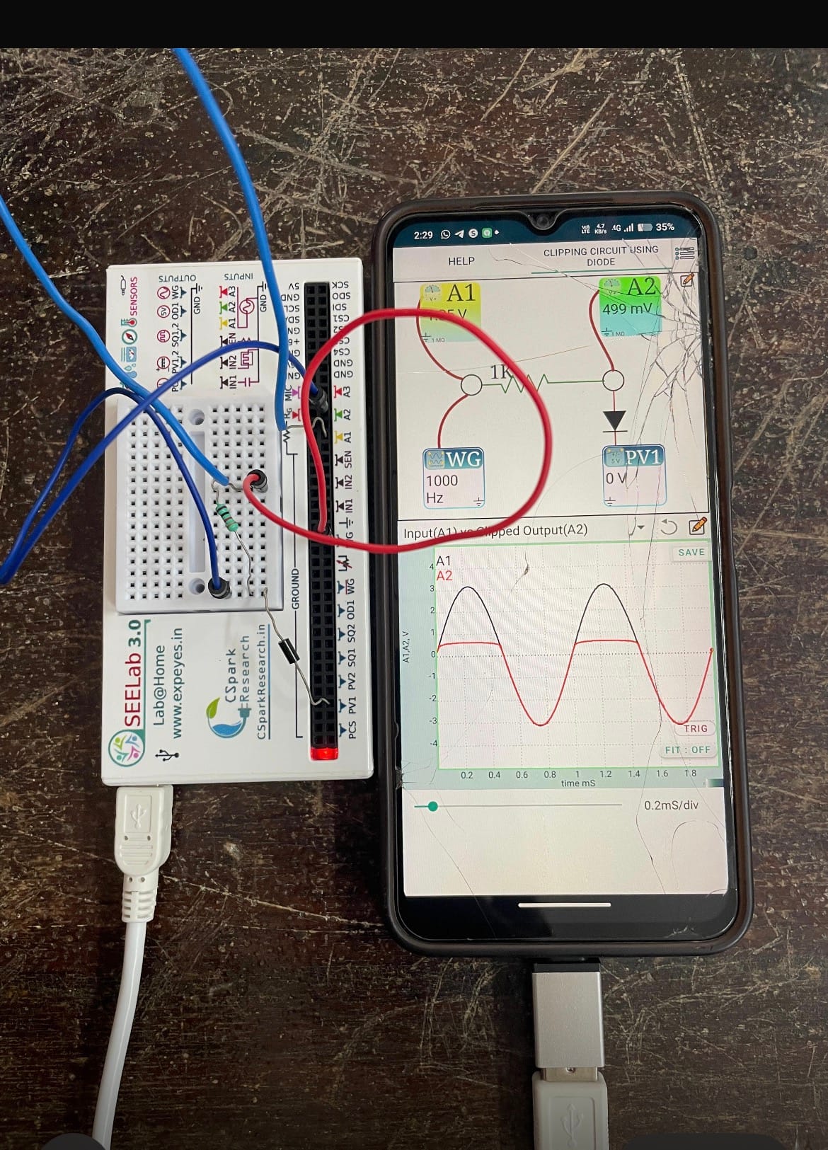
3CLIPPING CIRCUIT USING DIODE
The Clipping Circuit experiment demonstrates how a PN junction diode is used to limit or “clip” a portion of an input AC waveform above or below a predetermined voltage level without affecting the remaining part of the signal. Using ExpEYES, the waveform generator (WG) provides the input signal, while oscilloscope channels A1 and A2 are used to observe the input and clipped output waveforms, respectively. By changing the orientation of the diode, the circuit can function as either a positive or negative clipper. This experiment helps in understanding waveform limiting, voltage protection, and the application of clipping circuits in signal processing and electronic communication systems.
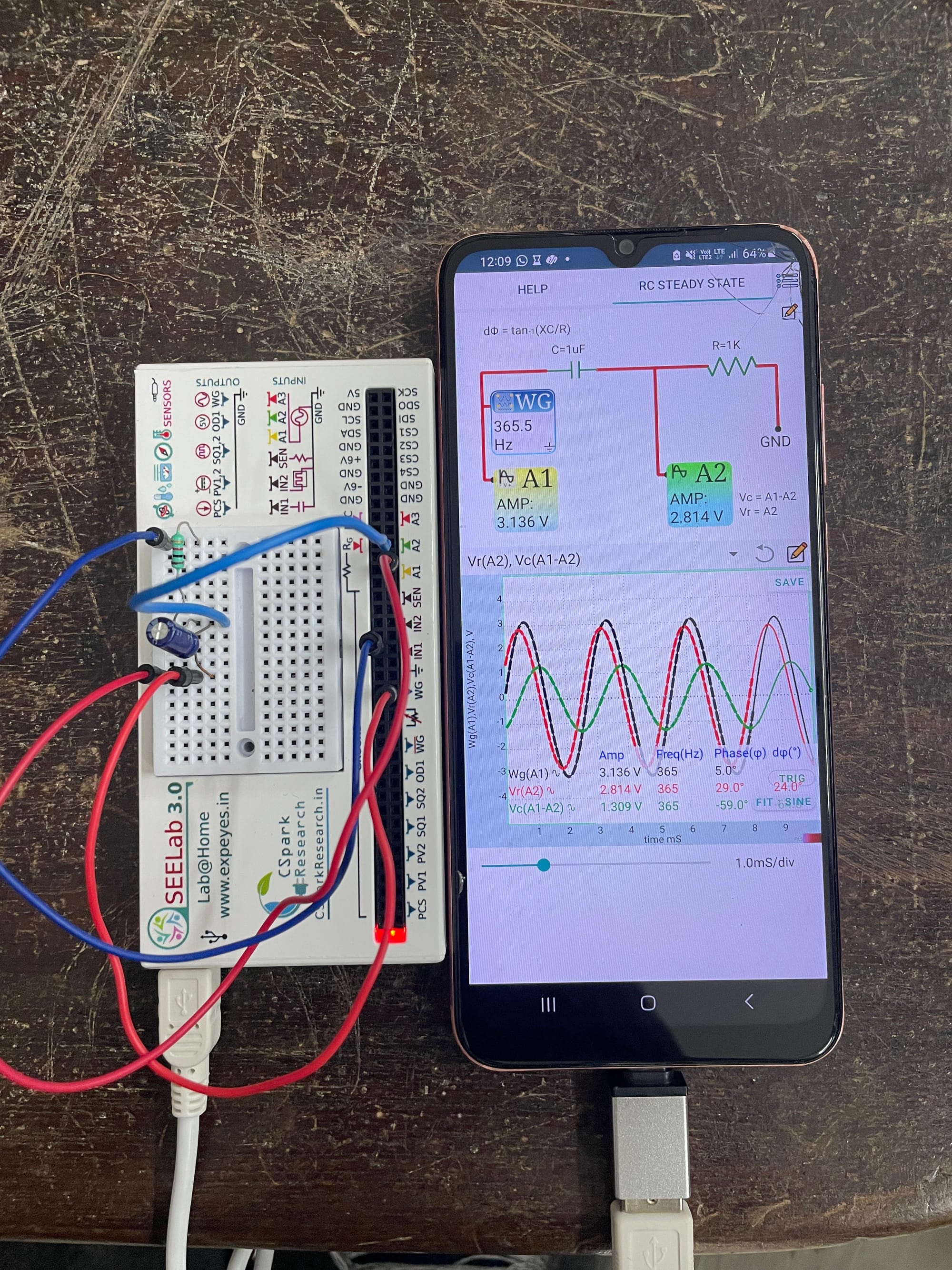
4.RC Steady State Response
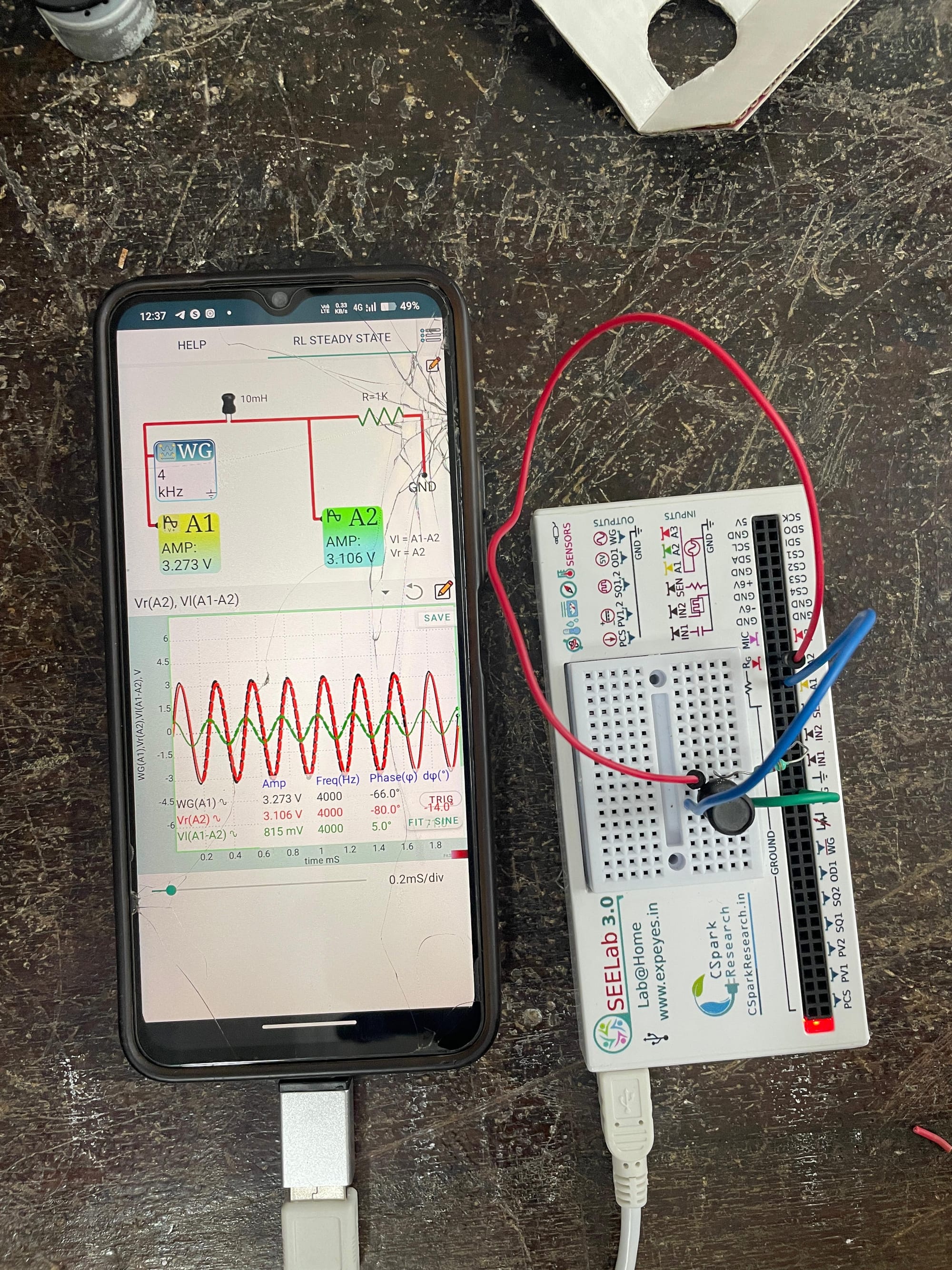
5.RL Steady State Response
The RL Steady State Response experiment demonstrates the phase relationship between voltage and current in a resistor-inductor (RL) circuit under a sinusoidal input. A 1 kΩ resistor and a 10 mH inductor are connected on a breadboard, and the waveforms are measured using ExpEYES/SEELab.
The voltage across the resistor is in phase with the current, while the voltage across the inductor leads the current by approximately 90°. By changing the input frequency, the phase difference and inductive reactance can be observed. This experiment verifies the theoretical behavior of RL circuits and improves understanding of phase relationships in AC circuits.
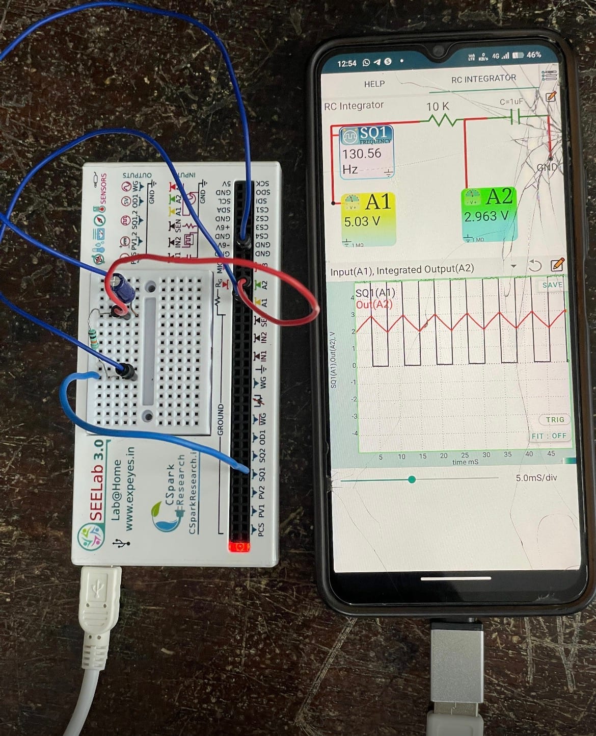
6.RC Integrator
The square wave is converted to a sine wave with this simple R-C circuit integrator.
7.AND Logic Gate
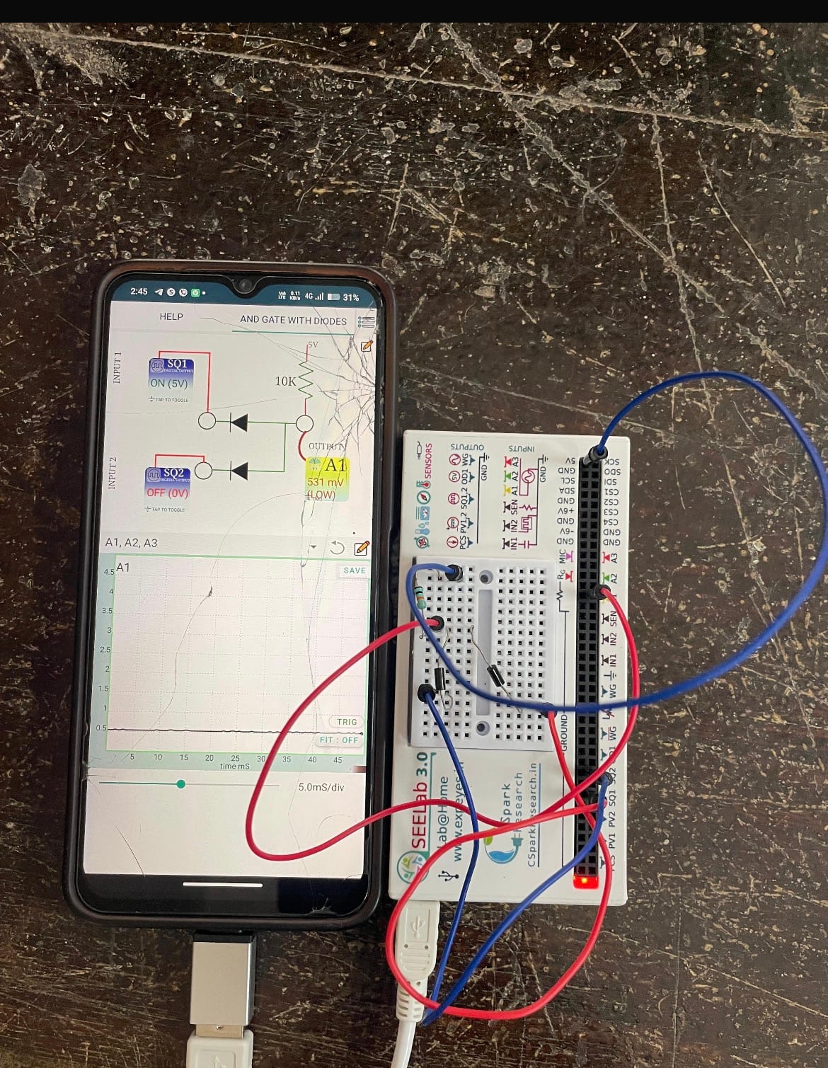
The AND Logic Gate experiment demonstrates the operation of an AND gate using PN junction diodes. Inputs are provided through SQ1 and SQ2, and the output is observed at A1 using ExpEYES/SEELab.
The output is HIGH (5 V) only when both inputs are HIGH. If one or both inputs are LOW, the output becomes LOW. This experiment verifies the truth table and working principle of the AND logic gate.
8.Ohm's Law with Alternating Current
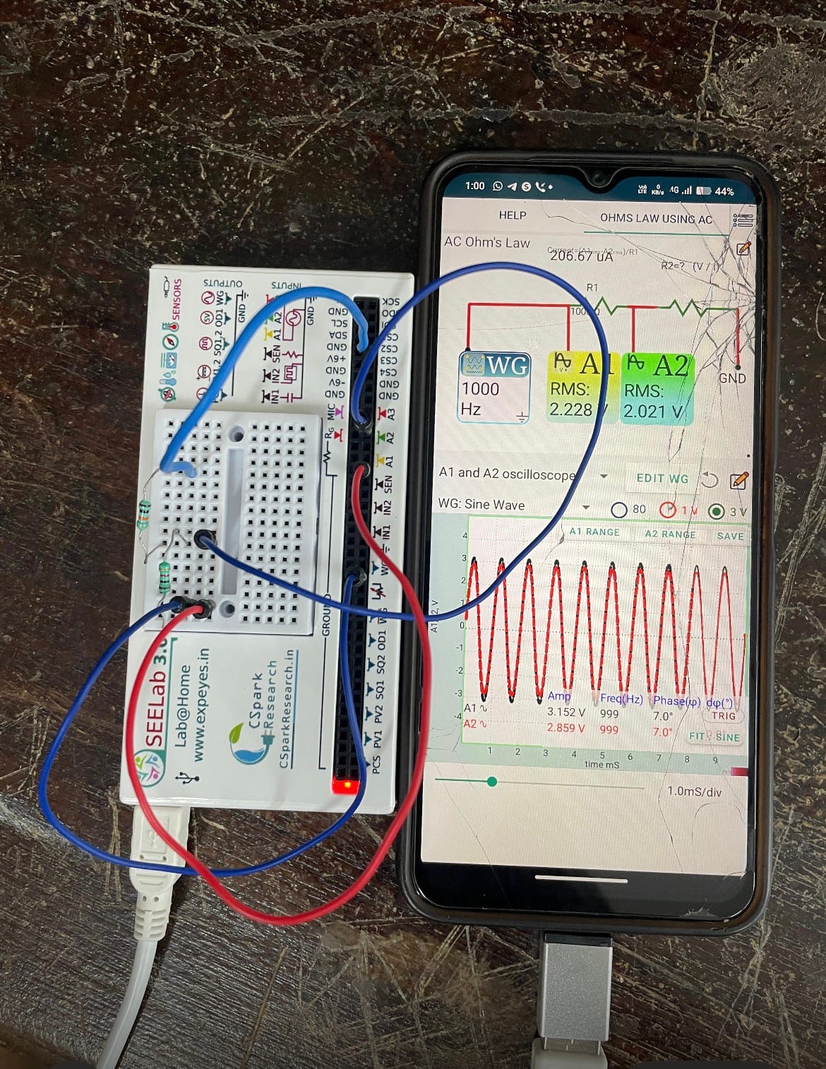
This experiment verifies Ohm's Law using alternating current (AC). A known 1 kΩ resistor and an unknown resistor are connected in series, and the RMS voltages are measured using ExpEYES/SEELab. The current is calculated from the voltage drop across the known resistor, allowing the unknown resistance to be determined.
The experiment also introduces the concept of RMS (Root Mean Square) value, which represents the equivalent DC voltage or current that produces the same power as an AC signal. The measured results closely match the expected resistor values, confirming the validity of Ohm's Law for AC circuits.
9.Full-Wave Rectifier Using PN Junctions
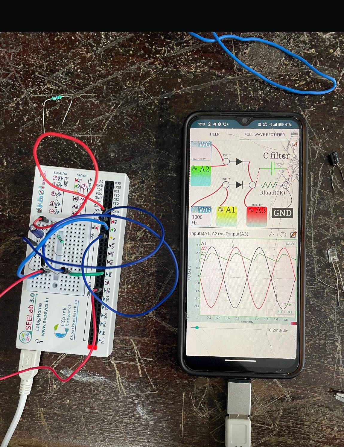
The Full-Wave Rectifier experiment demonstrates how two PN junction diodes convert both positive and negative half-cycles of an AC signal into a pulsating DC output. Two AC signals that are 180° out of phase are supplied by the WG and WG Bar outputs of ExpEYES/SEELab.
The output contains less ripple than a half-wave rectifier, making it more efficient for DC conversion. This experiment helps in understanding the working principle of full-wave rectification and the advantages of using both halves of the AC waveform.
10.Zener Diode V-I Characteristics
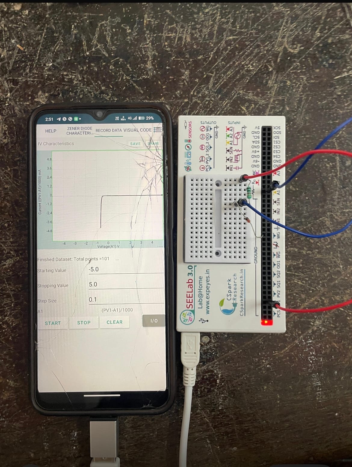
The Zener Diode V-I Characteristics experiment studies the behavior of a Zener diode under both forward and reverse bias conditions. By varying the input voltage from −5 V to +5 V, the diode's reverse breakdown voltage can be observed and its characteristic curve plotted.
Using ExpEYES/SEELab, the voltage across the diode and the current through it are measured to obtain the V-I graph. This experiment verifies the breakdown behavior of the Zener diode and compares the experimental results with theoretical characteristics.
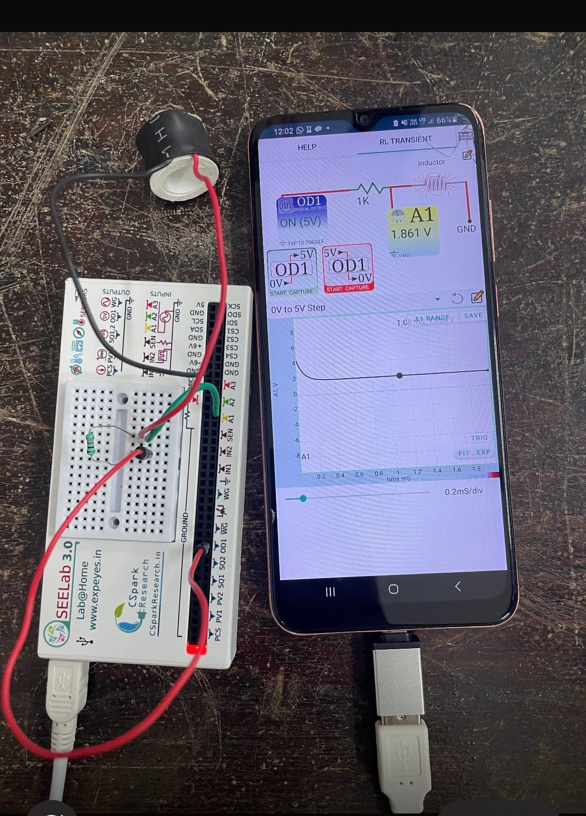
11.RL Transient Experiment
A simple RL transient circuit was set up using an inductor and a 1 kΩ resistor with the ExpEYES interface. A 0–5 V step input was applied, and the voltage response was observed using the A1 channel. The graph shows the transient behaviour of the inductor as the current changes with time.
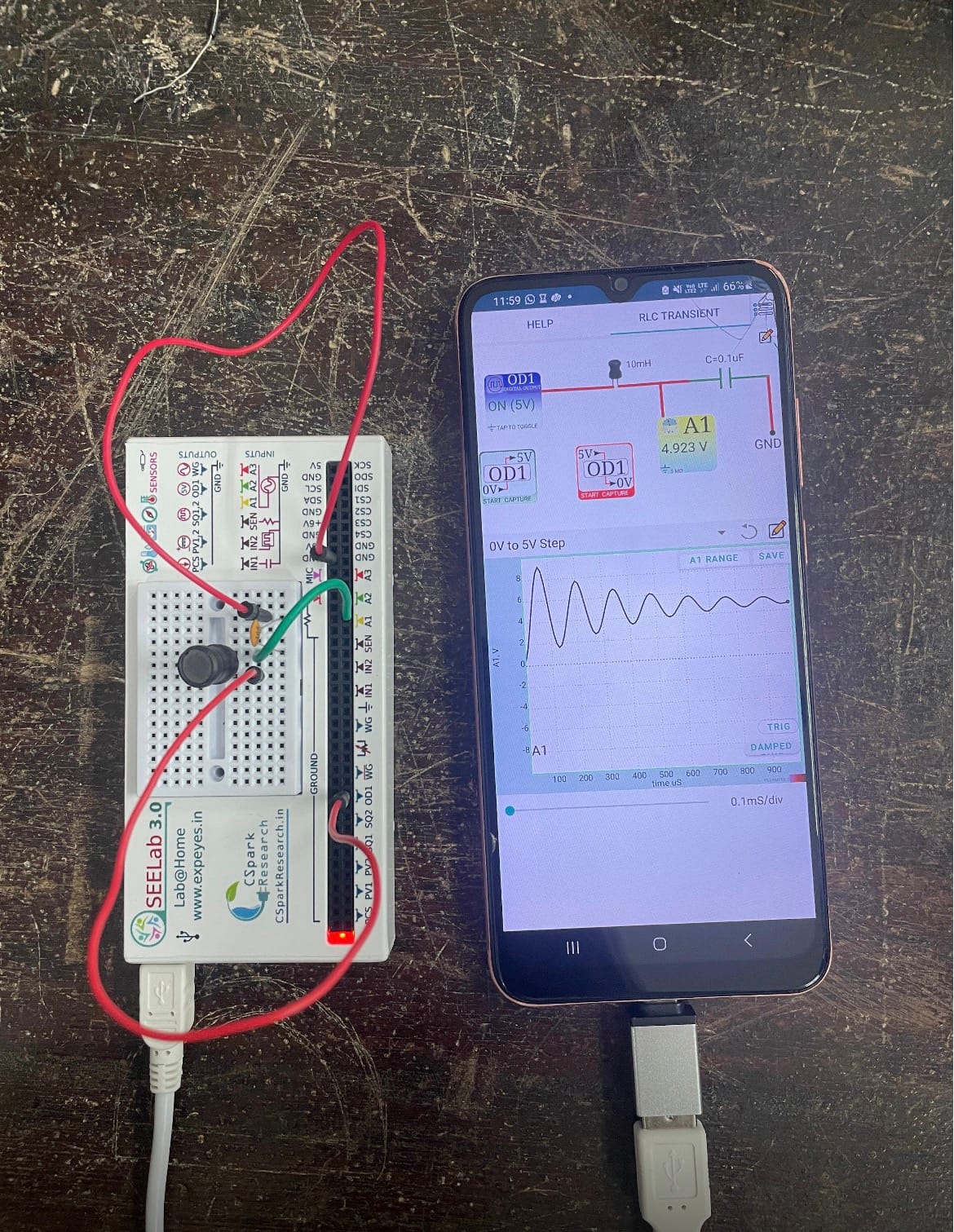
12.RLC Transient Response Experiment
An RLC circuit containing a 10 mH inductor and 0.1 µF capacitor was connected to an ExpEYES device. A 0–5 V step input was applied, and the transient voltage response was observed through the A1 channel. The graph shows damped oscillations, demonstrating the exchange of energy between the inductor and capacitor with gradual energy loss due to resistance.
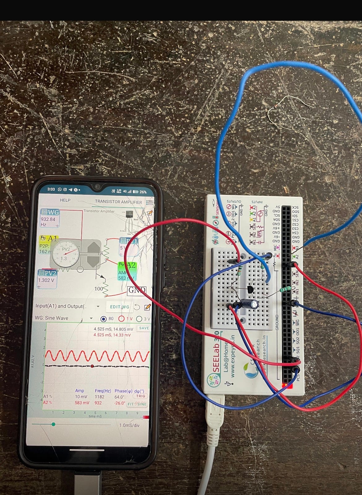
13.Transistor Amplifier Experiment
A transistor amplifier circuit was set up using the SEE Lab ExpEYES interface to study the amplification of an input signal. A sine wave was applied as the input, and the corresponding output signal was observed using the oscilloscope. The experiment demonstrates how a transistor can amplify a small electrical signal while producing a measurable phase difference between the input and output.
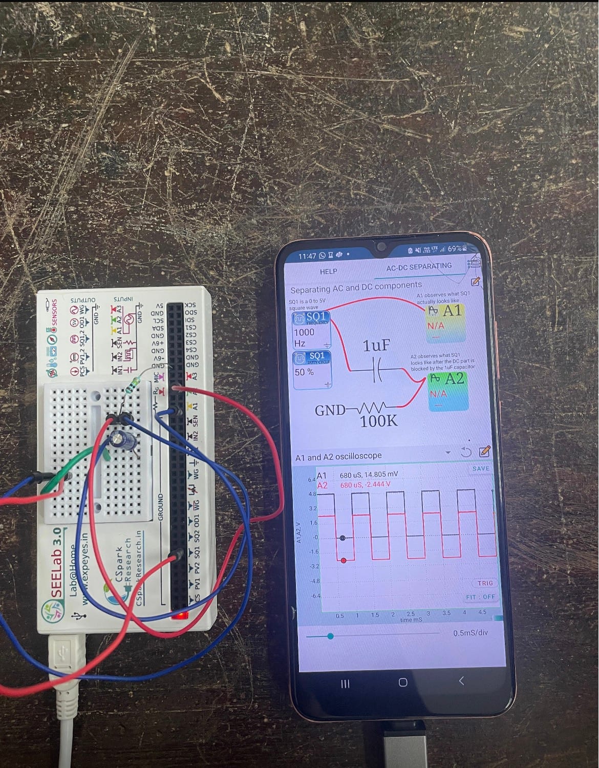
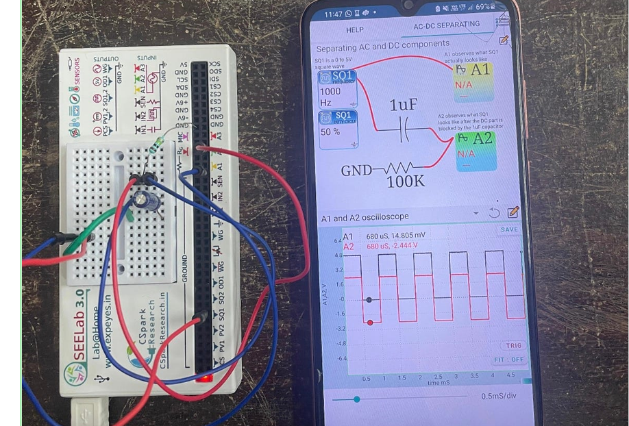
14.Separating AC and DC Components
This experiment demonstrates how AC and DC components of a signal can be separated using a capacitor. A square-wave signal is generated using the ExpEYES interface and passed through a 1 µF capacitor. The capacitor blocks the DC component while allowing the AC component to pass. The signals before and after the capacitor are observed using the oscilloscope in the ExpEYES application. This experiment helps illustrate the capacitive coupling and filtering of electrical signals.