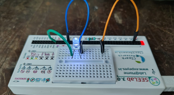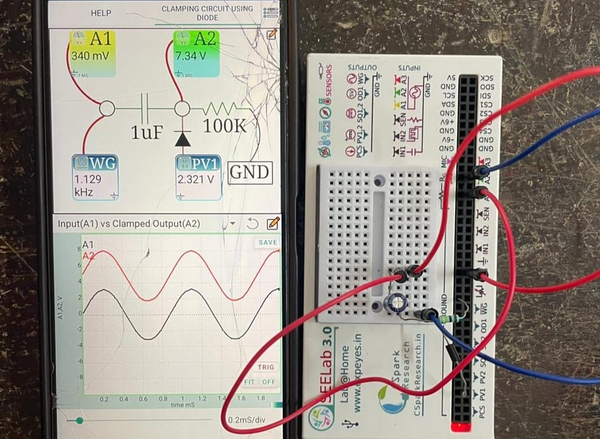
Logic Gates with Diodes #ExpEYES
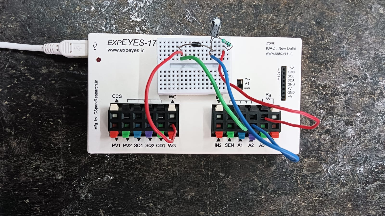
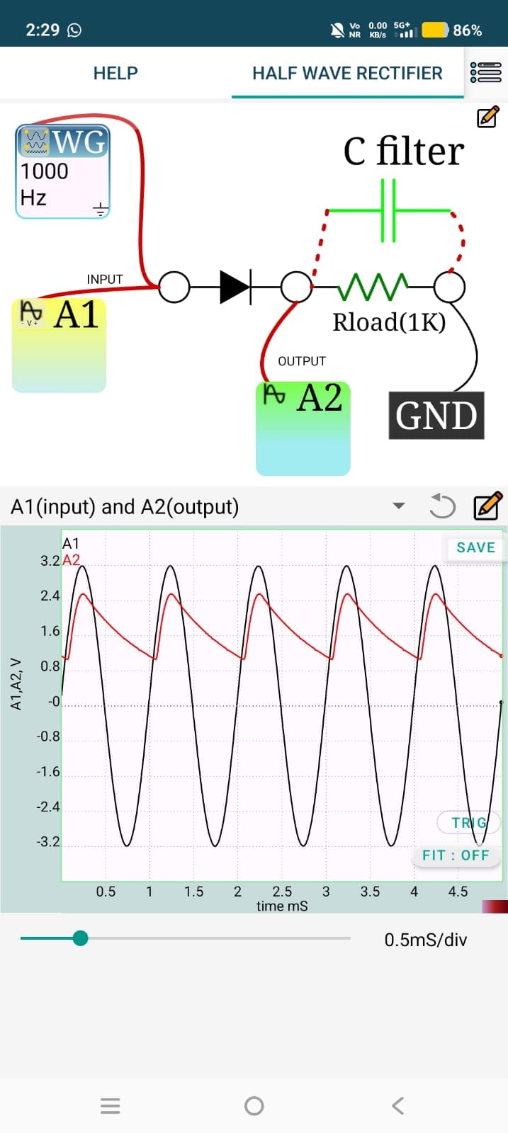
1.Half wave rectifier Half wave rectifier without filter The half-wave rectifier without a filter experiment using ExpEYES demonstrates how an alternating current (AC) signal is converted into a pulsating direct current (DC) using a single diode. The AC input is applied to the diode and load resistor, and the output voltage is observed using the SEELab3. During the positive half-cycle of the input, the diode conducts and the output follows the input. During the negative half-cycle, the diode blocks current, resulting in zero output. Thus, only one half of the AC waveform appears across the load, producing a pulsating DC output.
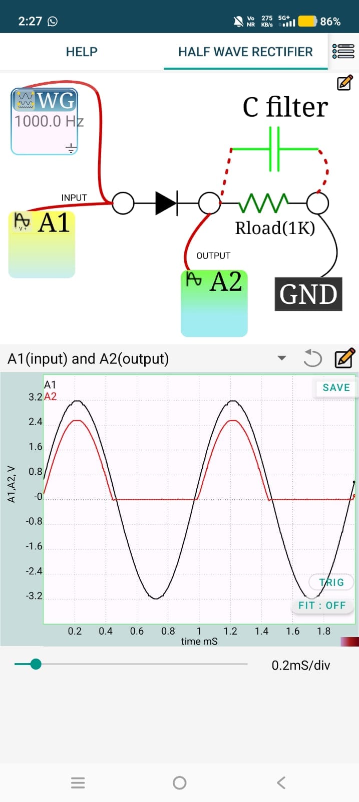
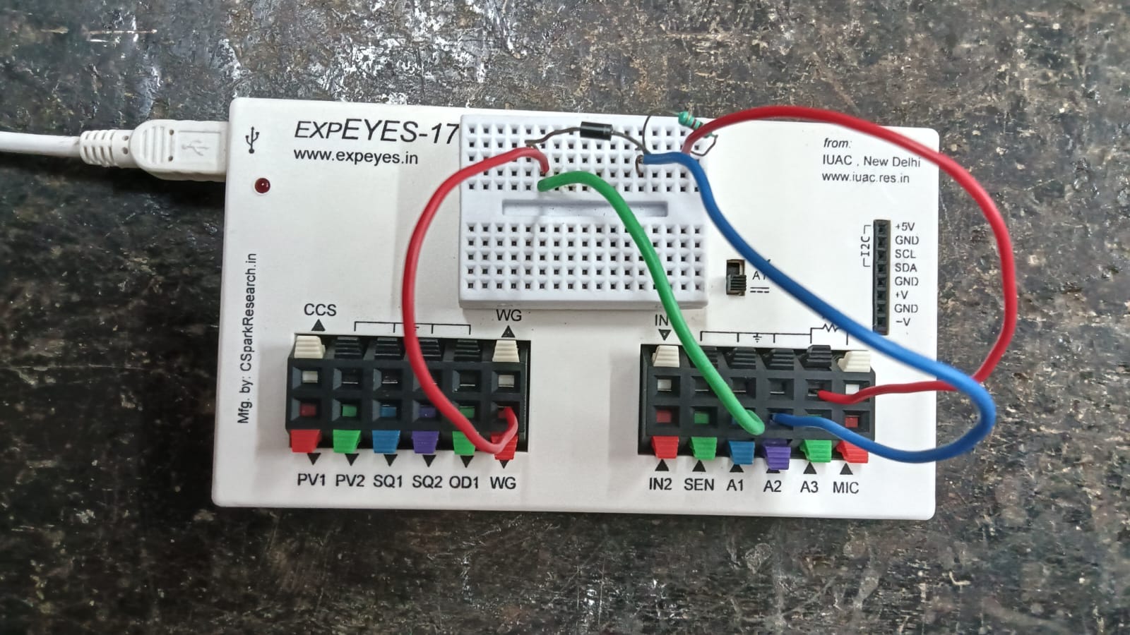
With filter A capacitor filter is connected across the load resistor to reduce the ripple and smooth the output voltage. Using ExpEYES, the input AC waveform and the rectified output waveform are displayed simultaneously. By comparing the waveforms before and after adding the filter capacitor, the reduction in ripple voltage and the improvement in the DC output can be clearly observed.
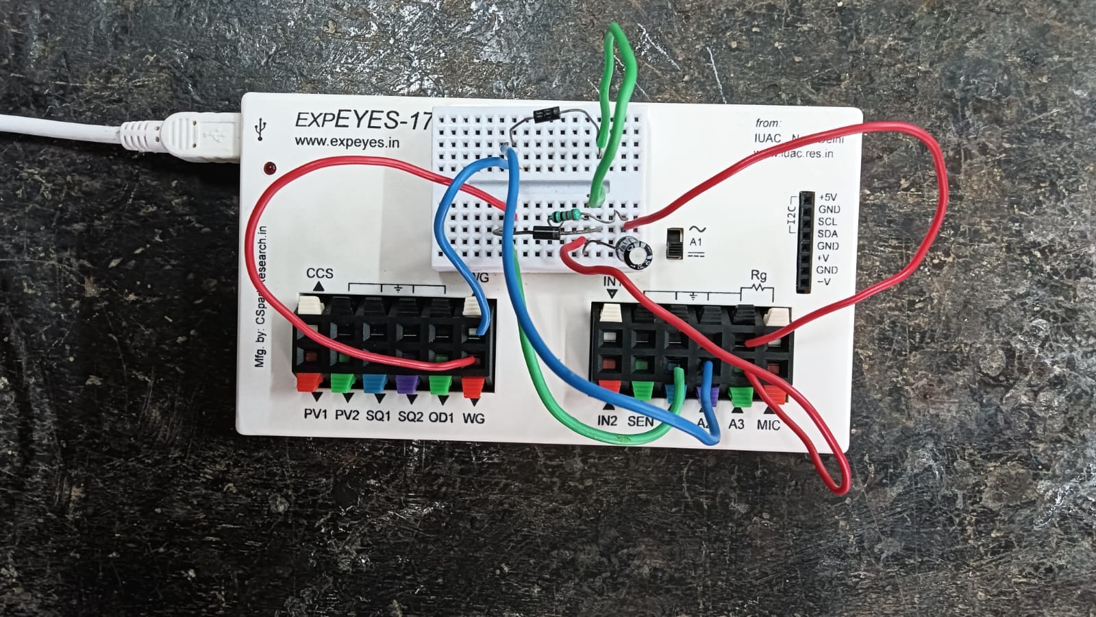
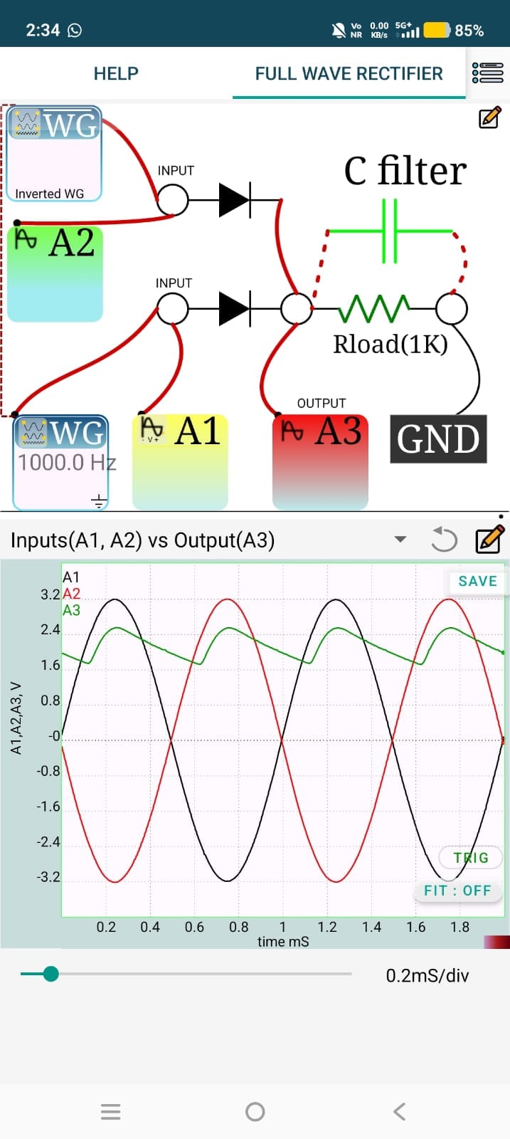
2.Full wave rectifier Without filter The Full-Wave Rectifier without Filter experiment demonstrates the conversion of an AC input signal into a pulsating DC output by rectifying both the positive and negative half-cycles of the input waveform. Using ExpEYES, the input AC waveform and the full-wave rectified output waveform are displayed and compared on the oscilloscope. The output consists of positive pulses with twice the frequency of the input AC signal but still contains significant ripple because no filter capacitor is used. This experiment helps in understanding the operation of full-wave rectification and the characteristics of unfiltered DC output.
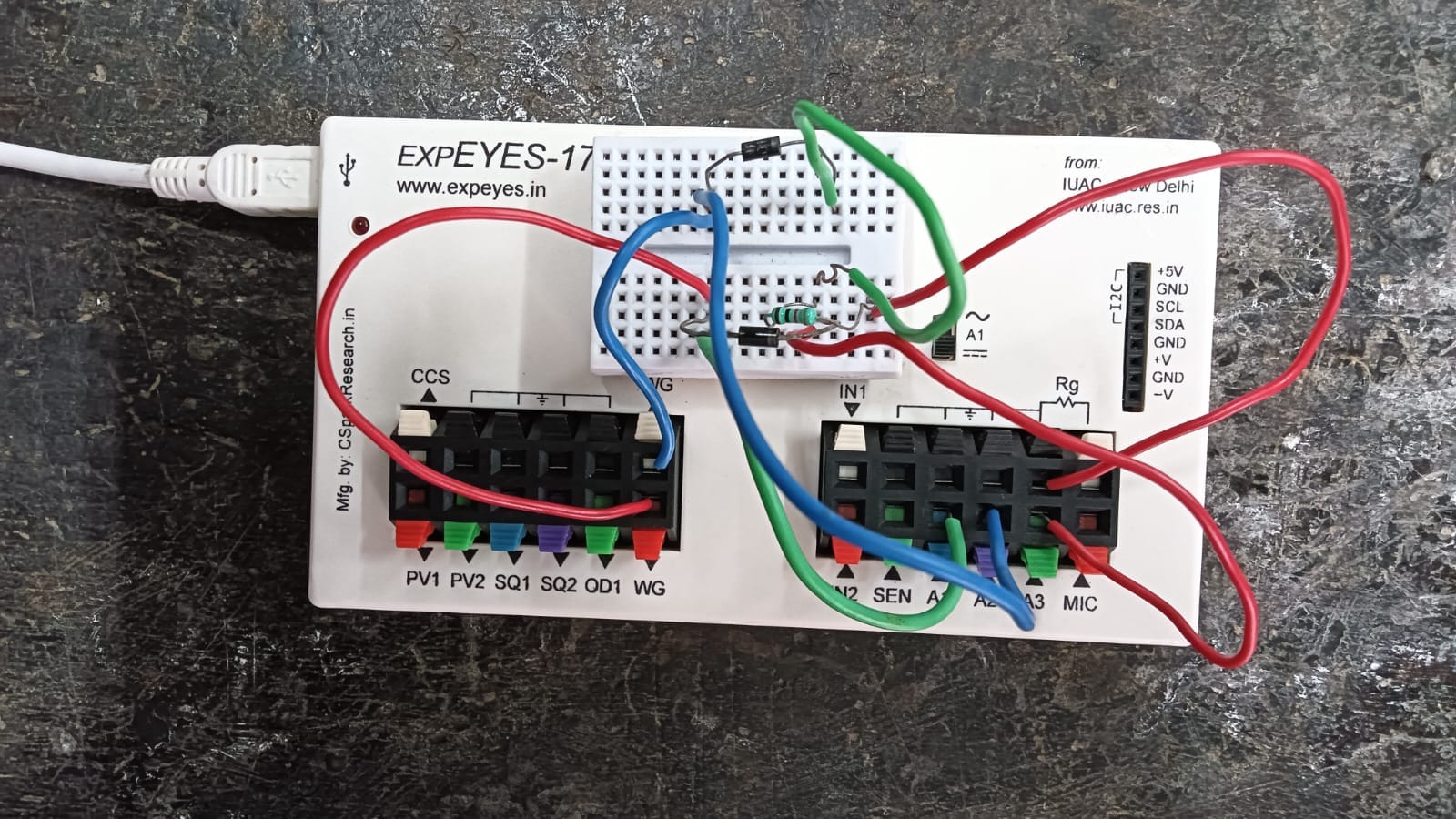
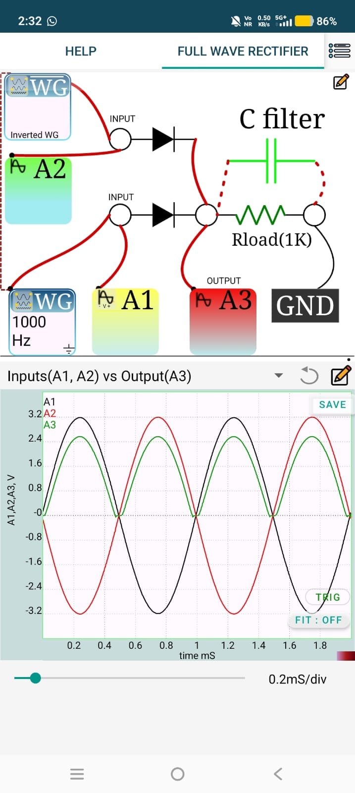
With filter A capacitor filter connected across the load resistor smooths the output by reducing ripple voltage. With ExpEYES, the input AC waveform and the filtered DC output are observed and compared on the oscilloscope. The experiment shows that the full-wave rectifier produces a higher average DC output with significantly lower ripple than a half-wave rectifier.
3.OR gate using diodes
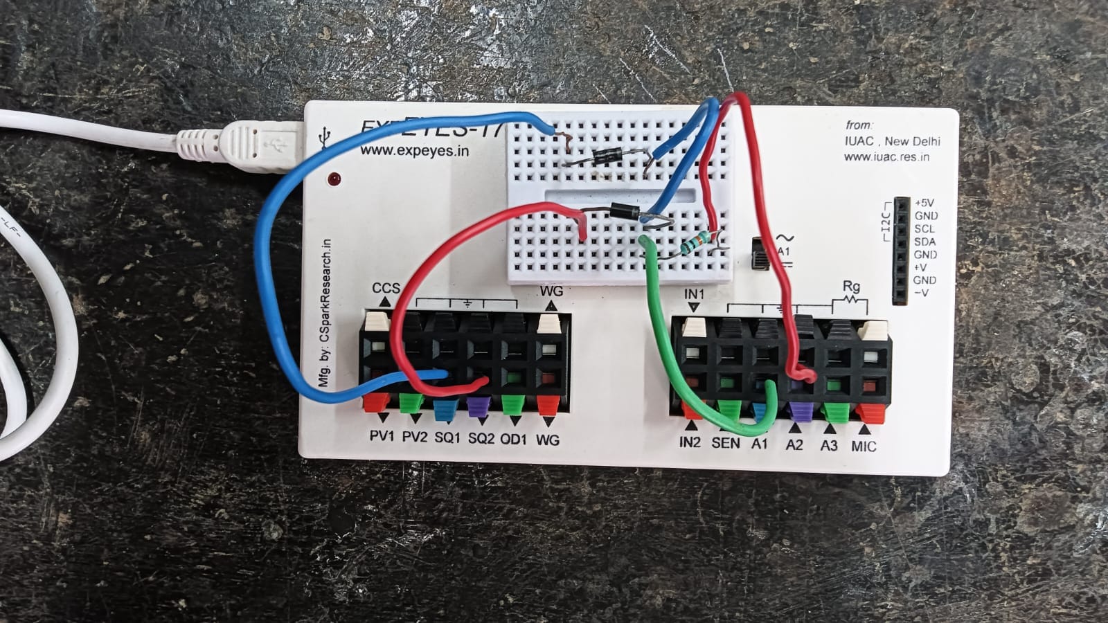
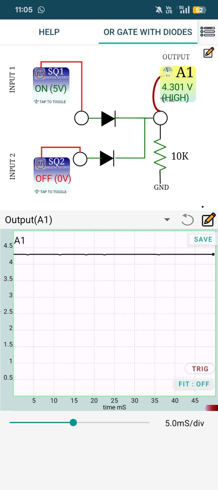
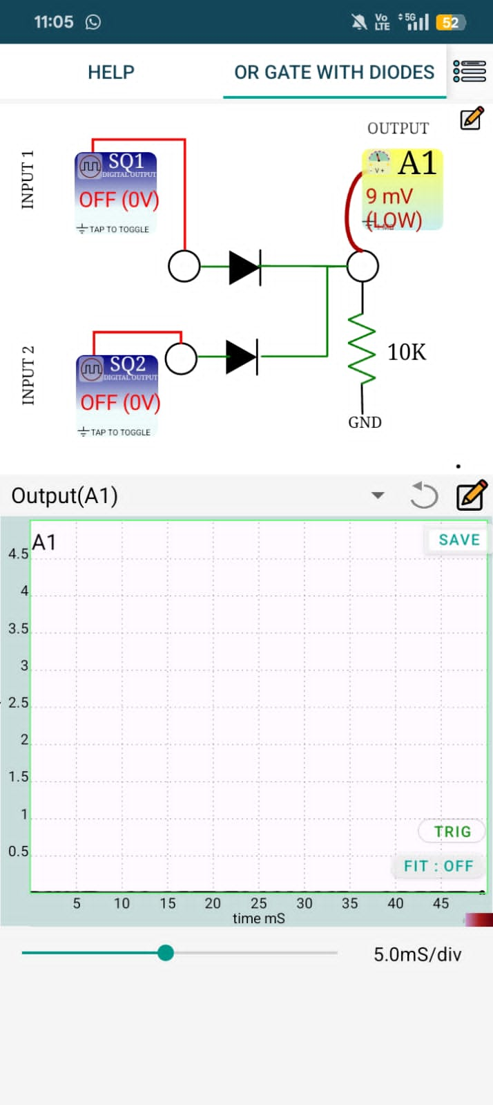
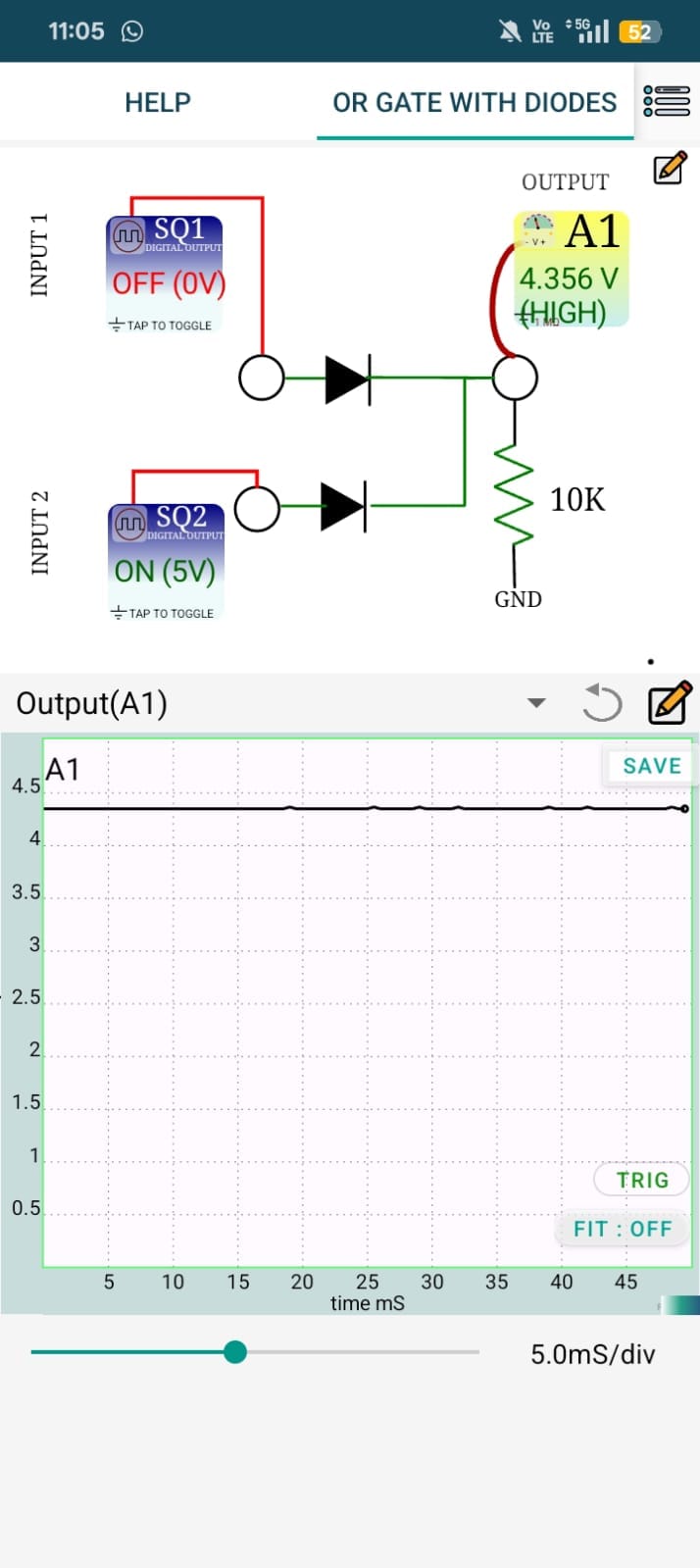
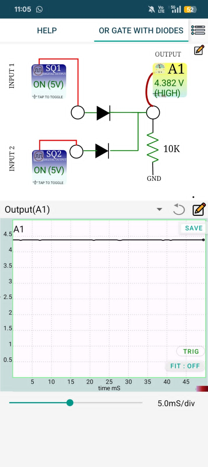
The OR Gate using Diodes experiment with ExpEYES demonstrates how diodes can be used to implement the logical OR operation. Two digital input signals are applied through diodes to a common output with a pull-down resistor. The output becomes HIGH whenever at least one of the inputs is HIGH and remains LOW only when both inputs are LOW, following the OR gate truth table.
Using ExpEYES, the input and output voltages are applied and monitored to verify the logical operation.
Diode VI characteristics
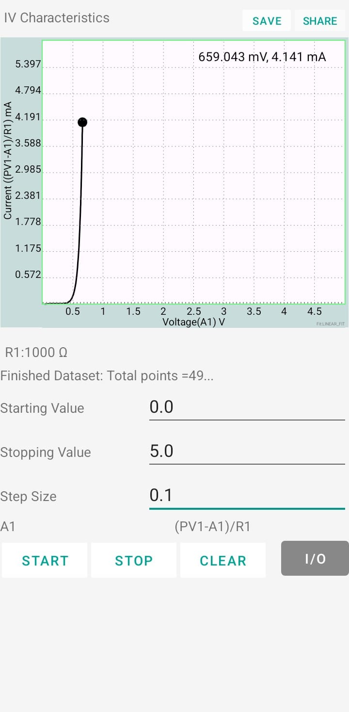
The Diode V–I Characteristics experiment using ExpEYES investigates the relationship between the voltage across a PN junction diode and the current flowing through it in both forward and reverse bias conditions. The diode voltage is varied using ExpEYES, and the corresponding current is measured automatically.
The recorded data is plotted as a V–I graph, allowing observation of the diode's threshold (cut-in) voltage in forward bias and the very small leakage current in reverse bias.
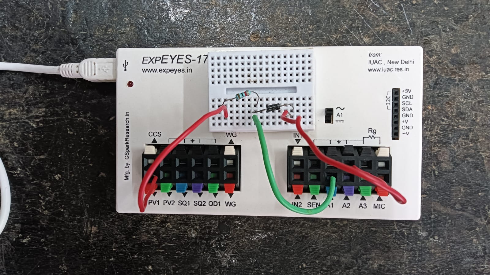
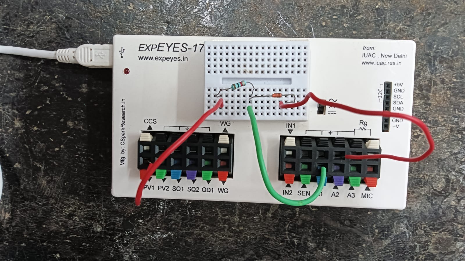
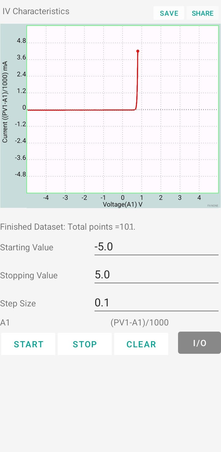
5.Zener diode characteristics The Zener Diode Characteristics experiment using ExpEYES studies the voltage-current (V–I) characteristics of a Zener diode in both forward and reverse bias. In forward bias, the diode behaves like a normal diode, while in reverse bias it maintains a nearly constant voltage after reaching its Zener breakdown voltage. Using ExpEYES, the voltage across and current through the Zener diode are measured and plotted to obtain its V–I characteristics. The experiment helps determine the Zener breakdown voltage and demonstrates the principle of voltage regulation, highlighting the use of Zener diodes in maintaining a stable output voltage in electronic circuits.
6.RC integrator
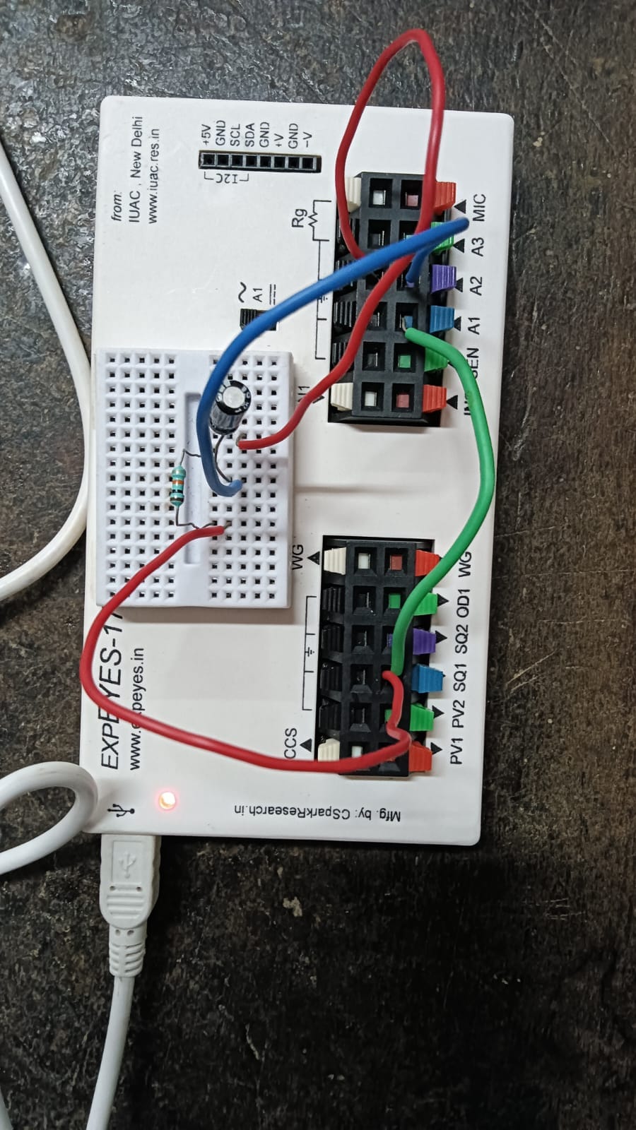
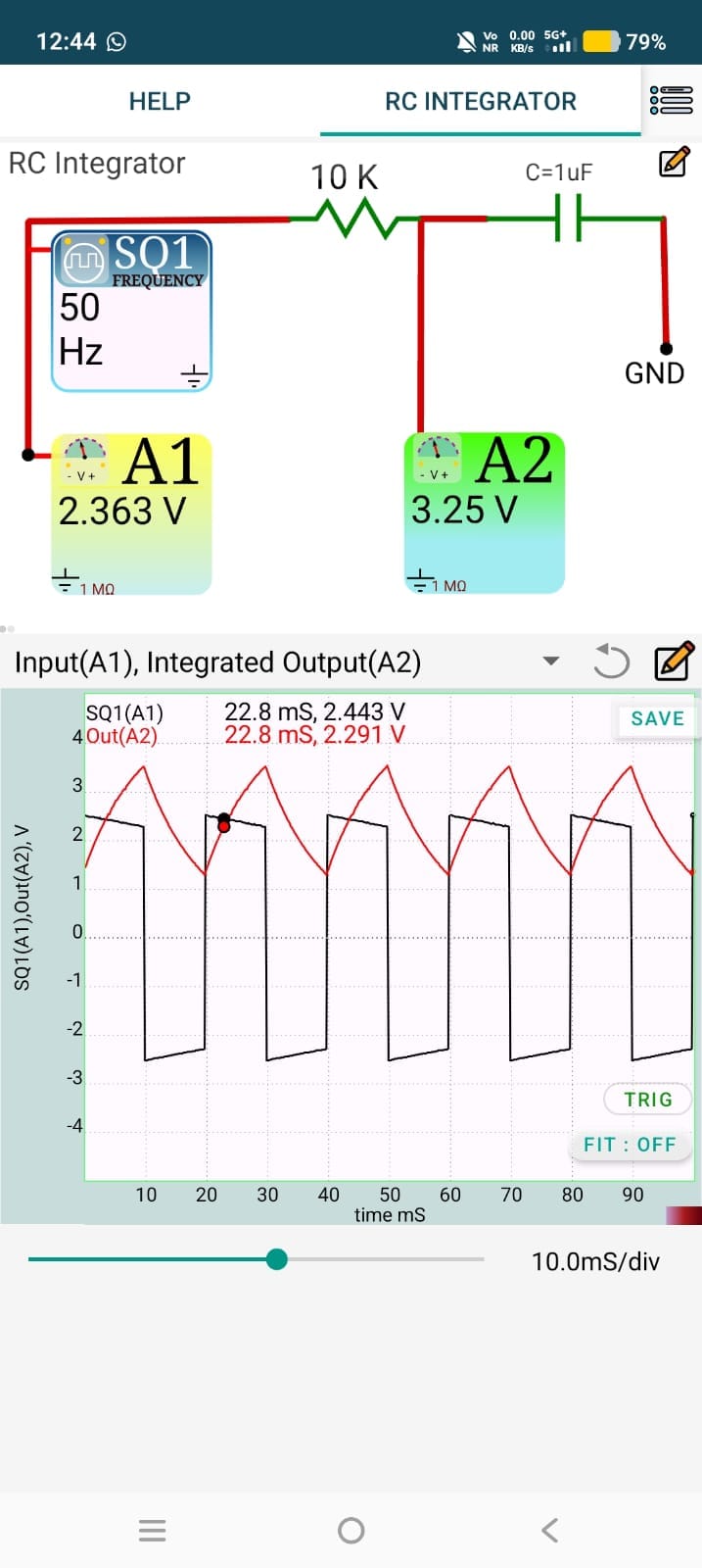
This experiment demonstrates how a resistor–capacitor (RC) circuit performs the mathematical integration of an input signal. A square-wave signal from the function generator is applied to the RC circuit, and the output is observed across the capacitor. The square wave is converted into an approximately triangular waveform.Using ExpEYES, the input and output waveforms are displayed simultaneously.
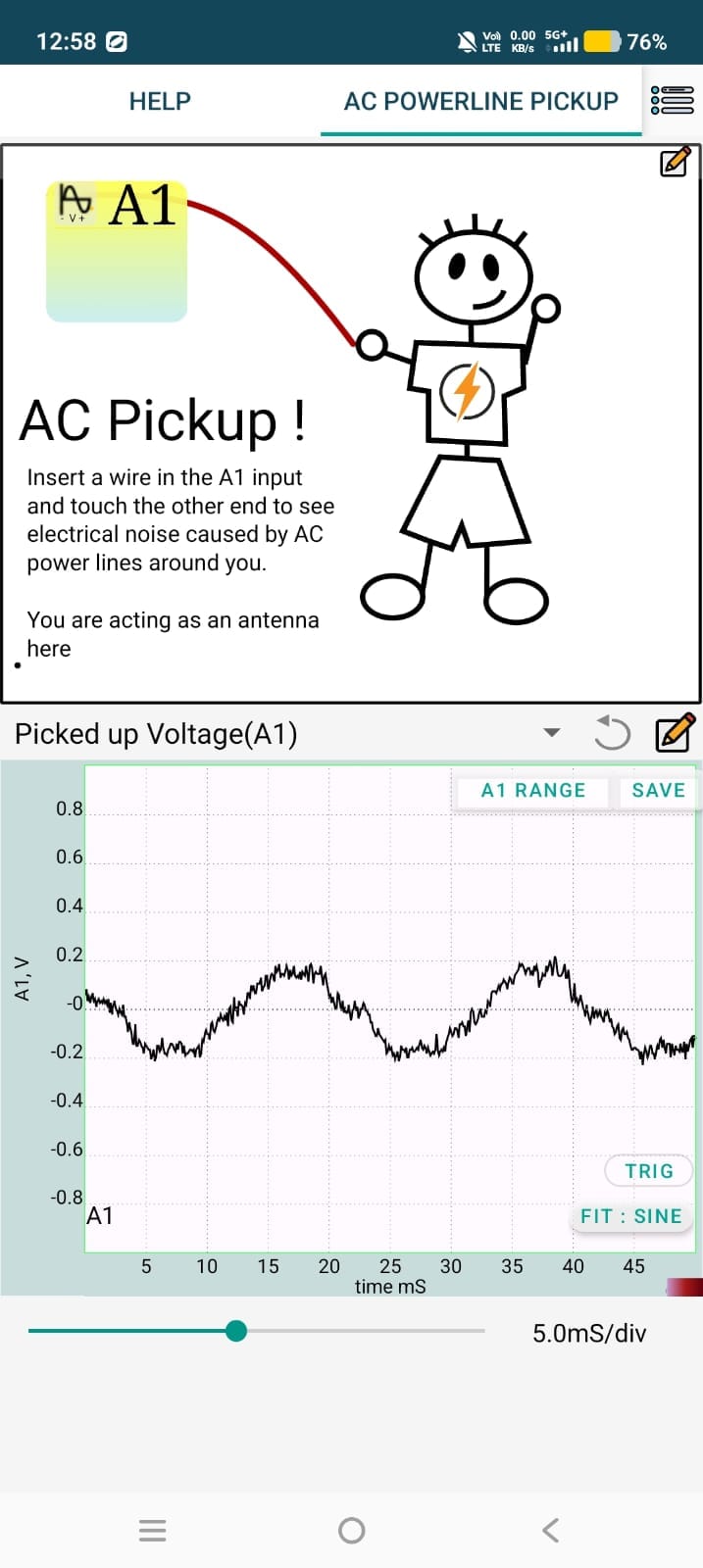
7.AC powerline pickup This experiment demonstrates how the human body and a wire can act as an antenna, picking up electromagnetic interference from nearby AC power lines. One end of a wire is connected to the A1 input of ExpEYES, while the other end is touched by the user. The induced AC voltage is measured and displayed as a waveform on the oscilloscope.
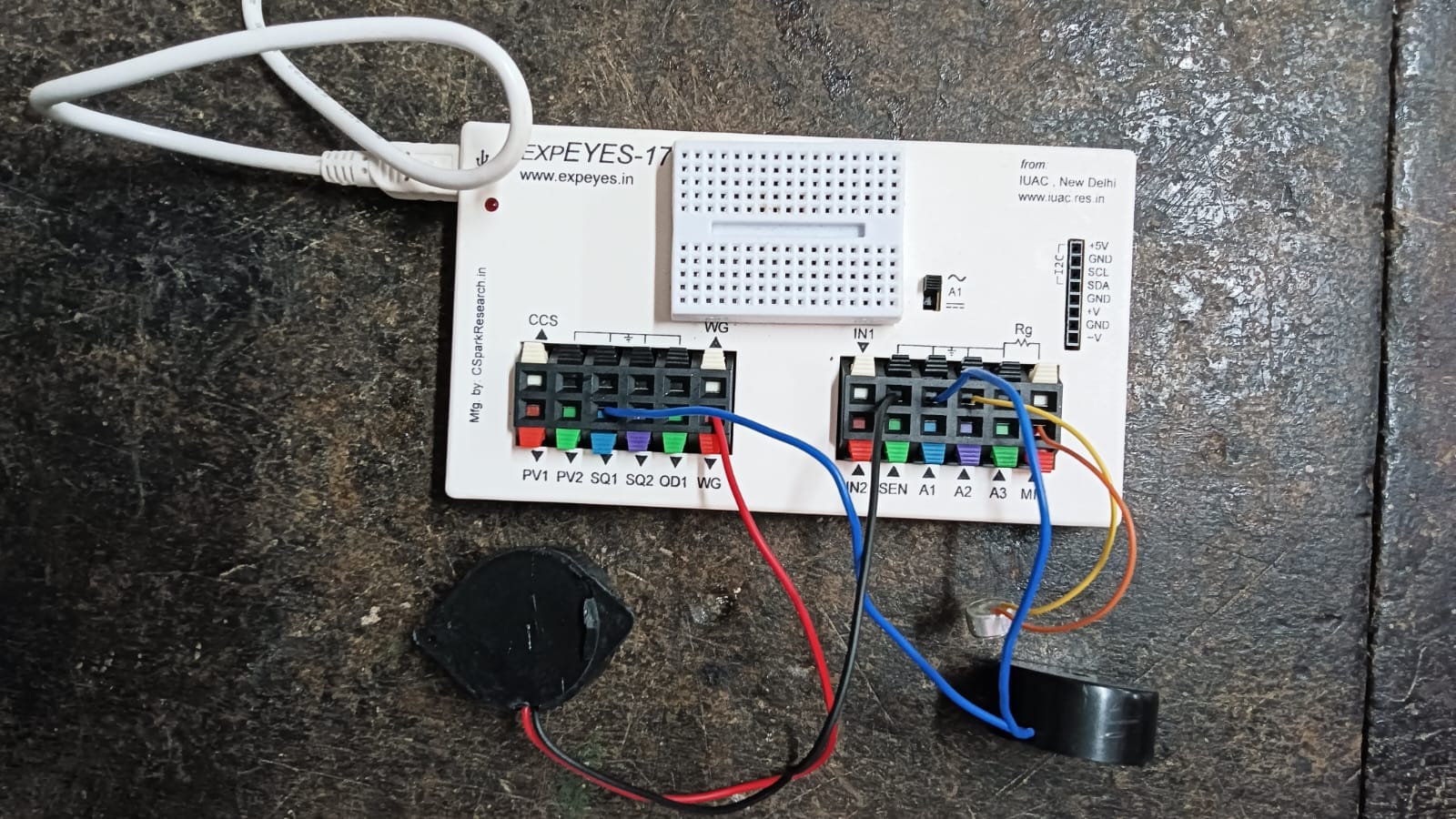
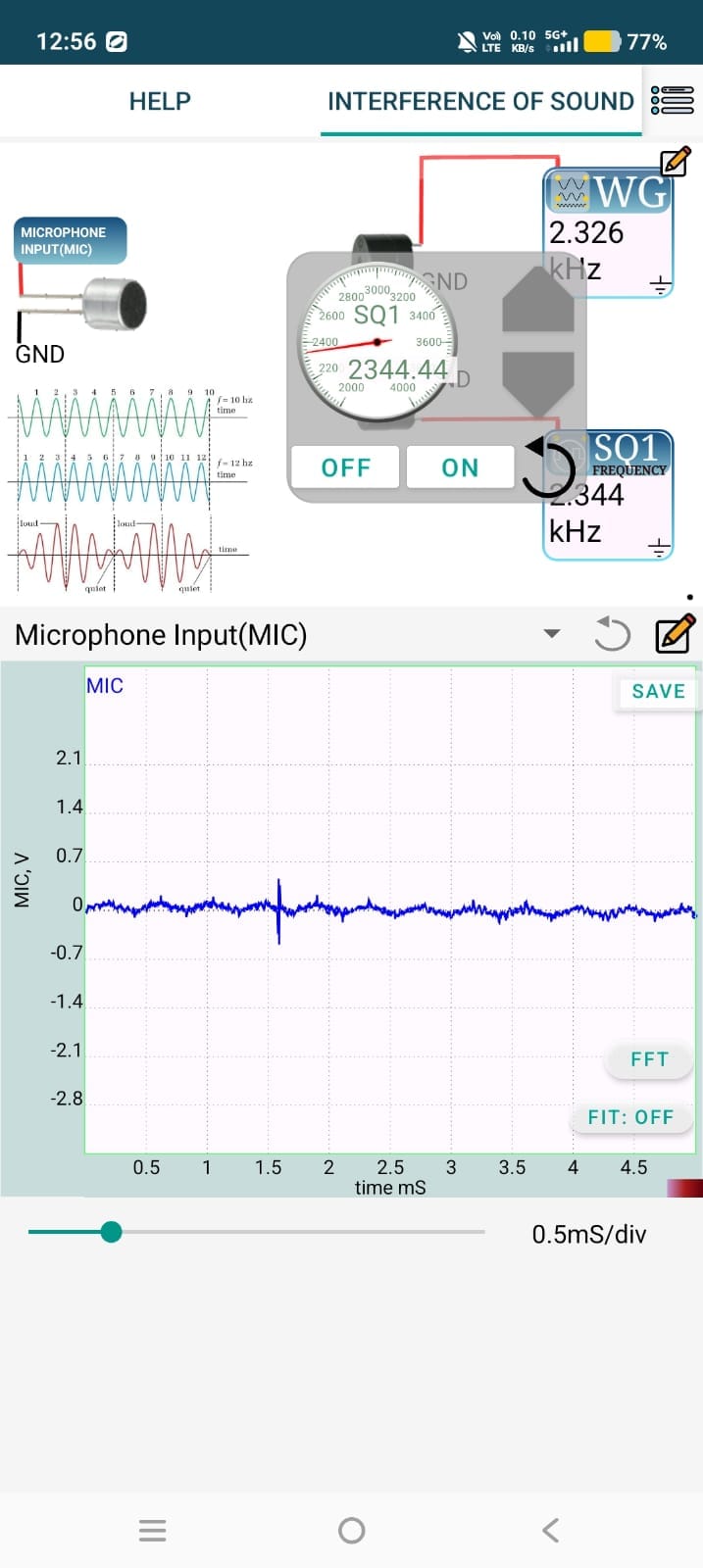
8.Interference of sound This experiment demonstrates the superposition of sound waves produced by two buzzers driven at same or different frequencies. The sound waves combine in air, producing constructive and destructive interference. A microphone connected to ExpEYES detects the combined sound signal, which is displayed and analyzed on the oscilloscope. By varying the frequency of one buzzer, beat patterns can be observed.
9.RC Transient
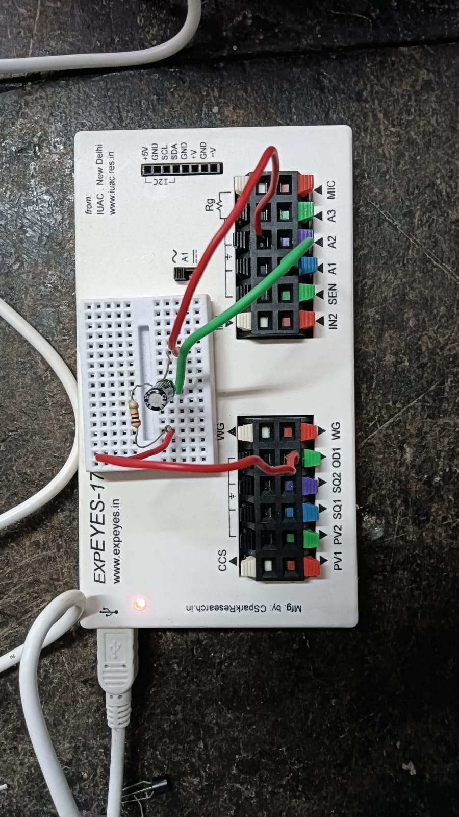
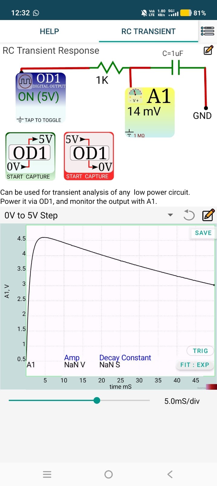
The RC Transient Response experiment using ExpEYES studies the charging and discharging behavior of a capacitor in an RC circuit when a step voltage is applied. ExpEYES generates a step input and measures the voltage across the capacitor as a function of time.
The observed voltage changes exponentially during charging and discharging.
10.RLC Transient
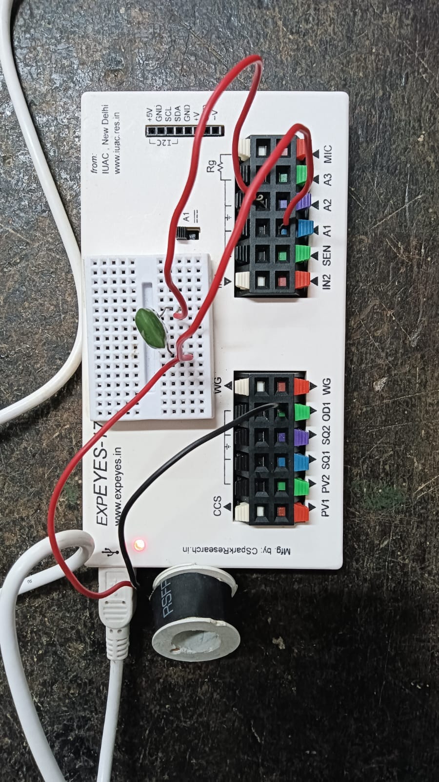
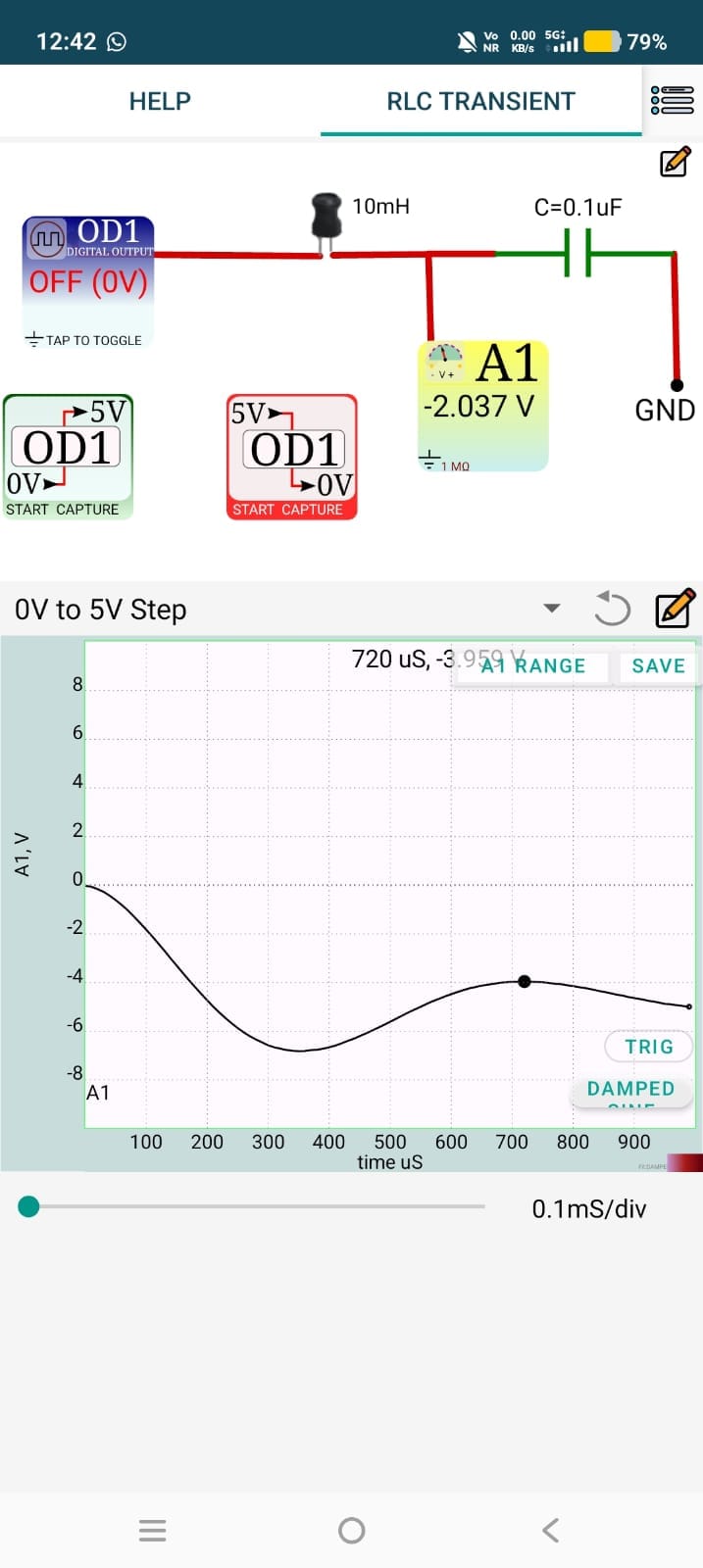
This experiment studies the transient behavior of a series RLC circuit containing a resistor, inductor, and capacitor. A step or pulse voltage is applied to the circuit, and the voltage across the circuit is measured as a function of time using ExpEYES. The resulting waveform shows the transient oscillations and their decay with time.
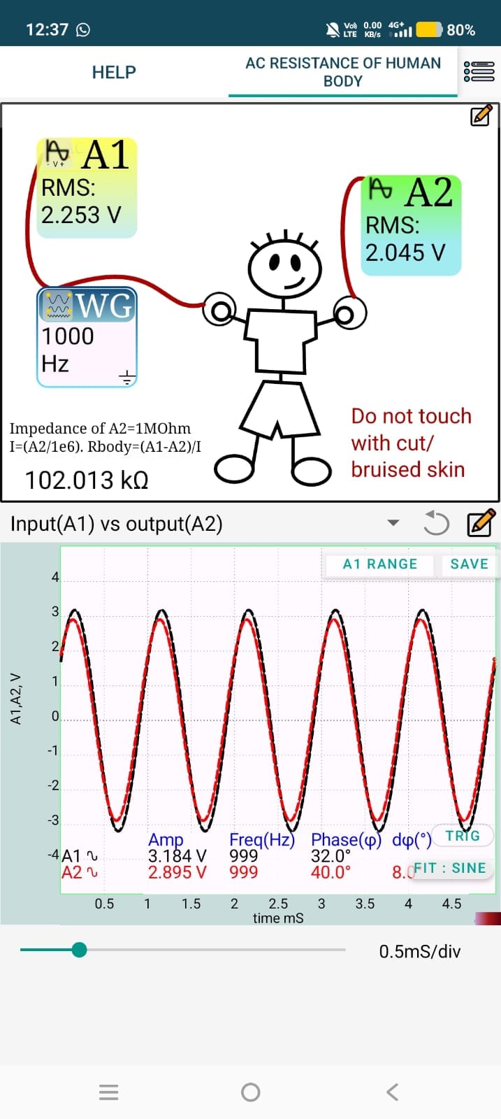
11.AC resistance of human body Using this experiment we can measure the approximate resistance of the human body to a low-amplitude, safe AC signal. The subject gently touches the electrodes connected to the ExpEYES device, and the resulting voltage and current are measured to estimate the body's AC resistance. It demonstrates that the human body behaves as an electrical conductor with resistance that varies depending on factors such as skin moisture, contact area, and pressure.
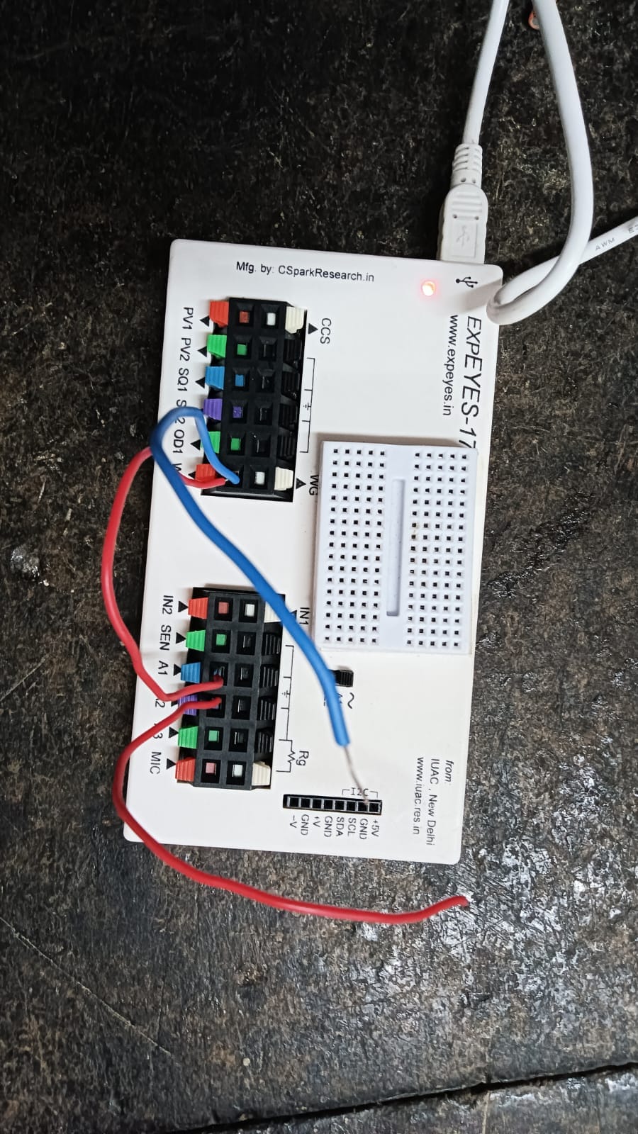
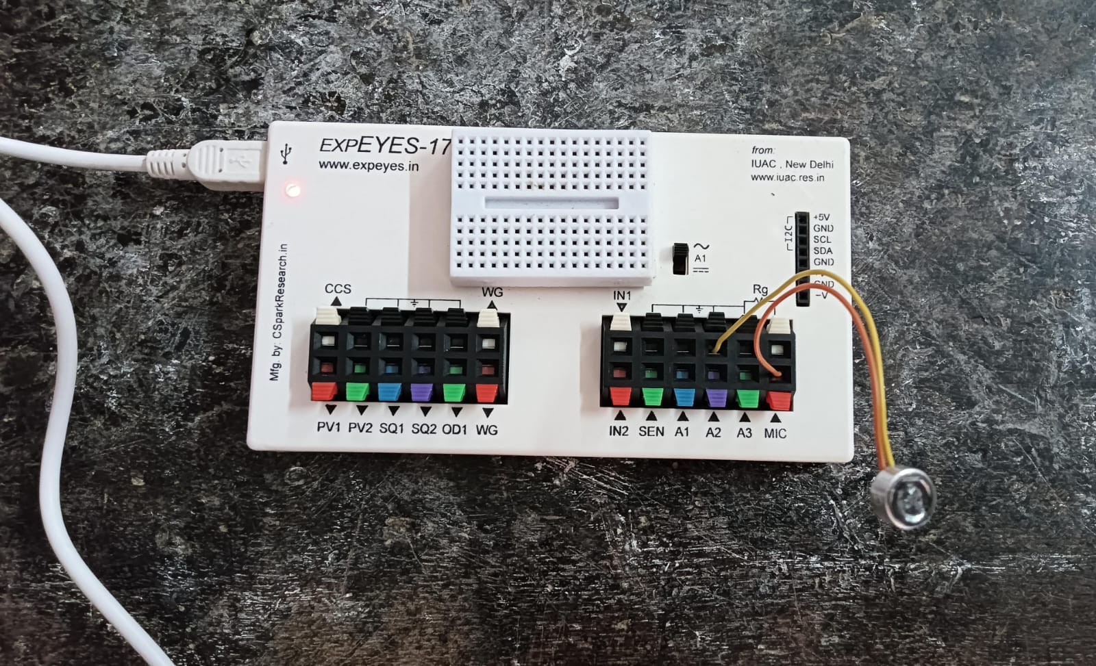
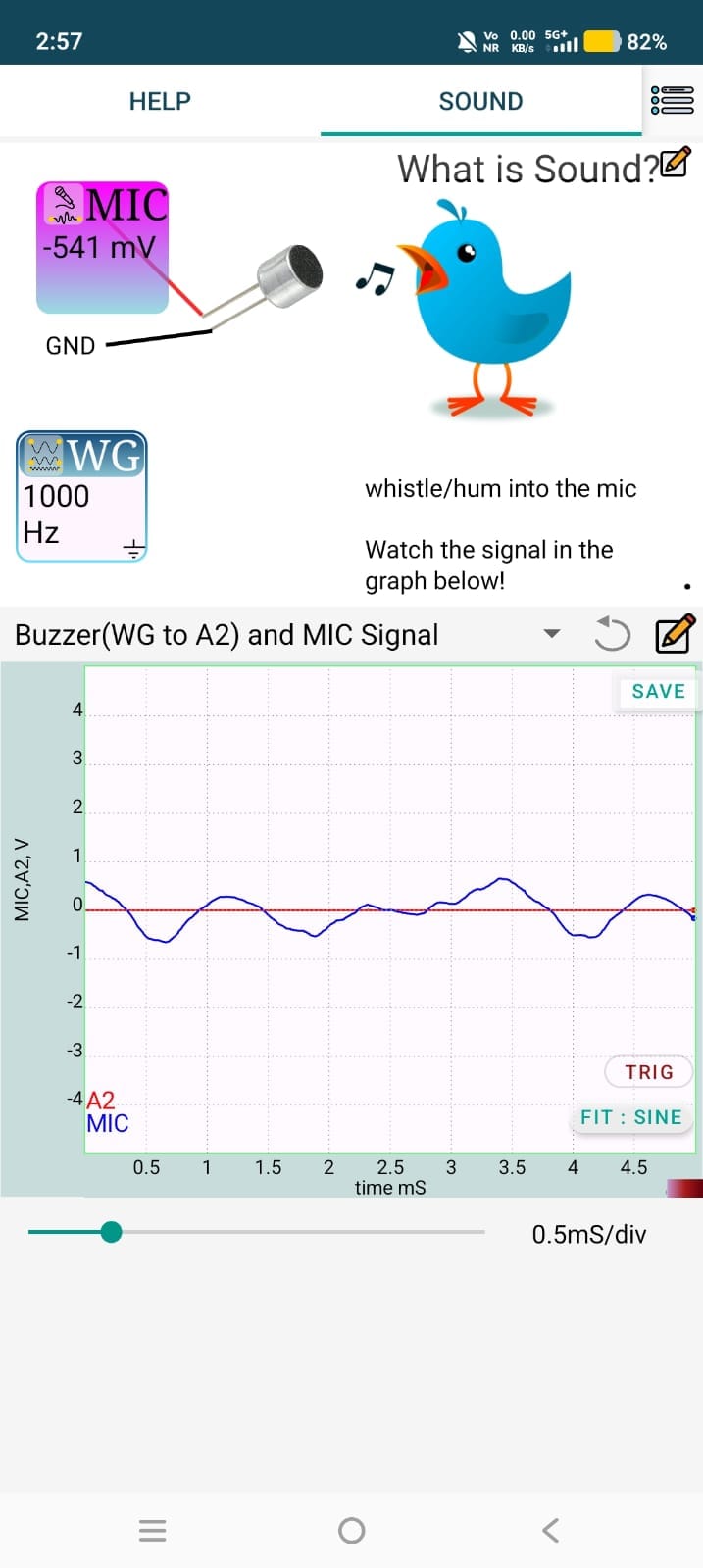
12.Sound In this experiment, the ExpEYES device is used to study how a microphone converts sound waves into electrical signals. When sound waves strike the microphone diaphragm, it vibrates and produces a corresponding electrical voltage. The generated signal is observed and analyzed using the ExpEYES software, allowing the waveform of the sound to be visualized in real time. By speaking, clapping, or producing different tones near the microphone, variations in amplitude and frequency can be observed.
13.Frequency response of piezo buzzer
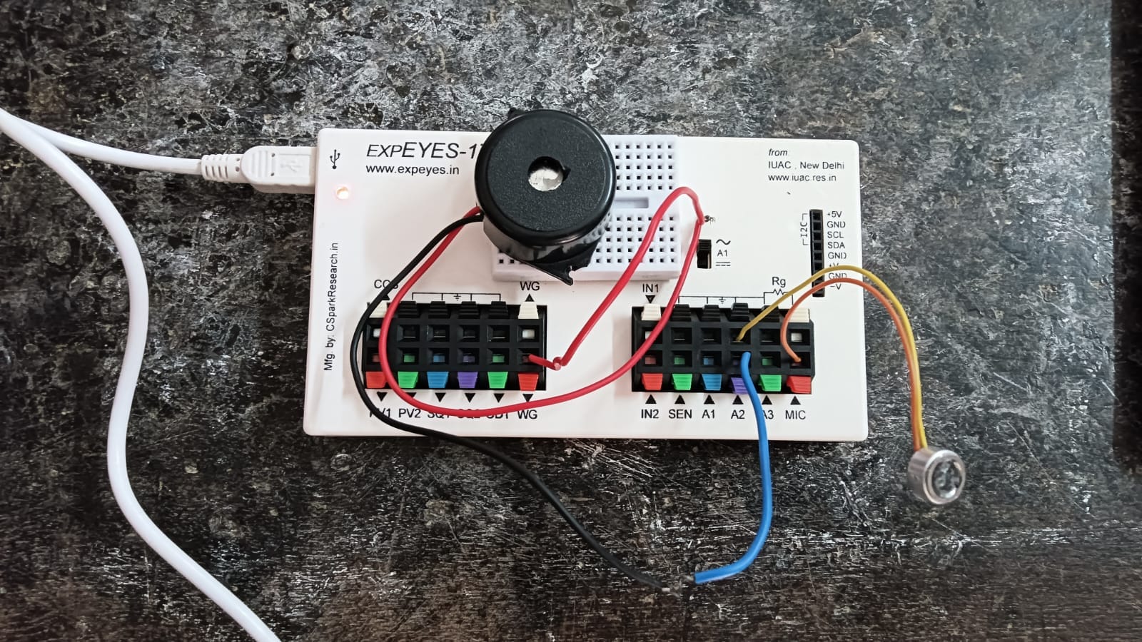
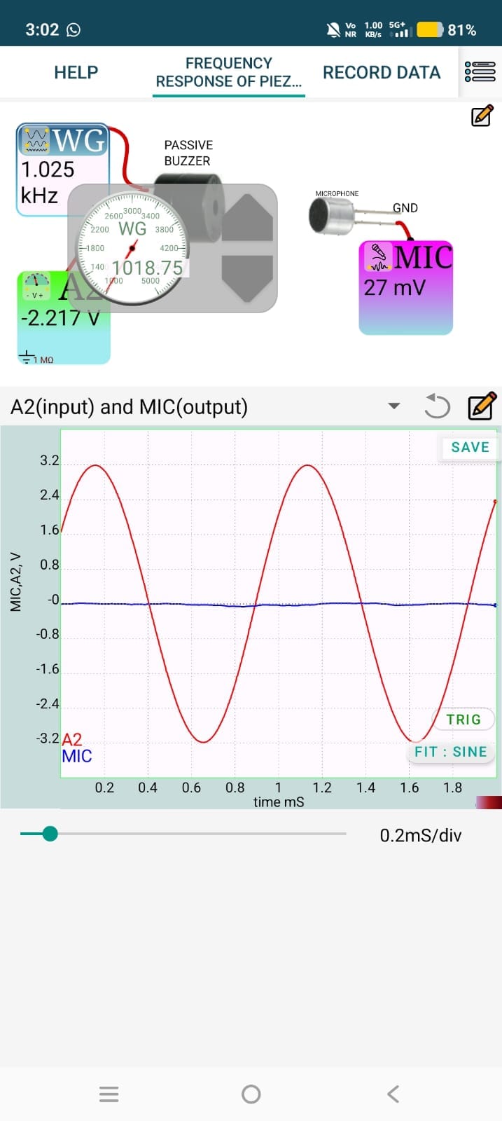
The Frequency Response of a Piezo Buzzer experiment using ExpEYES investigates how the sound output of a piezo buzzer varies with the frequency of the applied electrical signal. The buzzer is driven by a signal generator in ExpEYES, and the input frequency is varied over a selected range while the sound intensity is observed or measured using a microphone.
The frequency response is plotted by recording the buzzer's output at different frequencies.