Calibrating SEELab’s Analog Features for Maximum Accuracy

The hardware design of SEELab-3.0 aims to achieve the maximum possible performance from a very conservative bill of materials. There are several analog components such as Op-amps, voltage dividers, and level-shifters involved in input signal processing that have inherent offsets and slopes that must be corrected in order get the best results. Similarly, some analog output signals from SEELab are also modified by buffers, amplifiers, and level shifting circuits.
One way to improve the initial accuracy is to choose high performance analog components that are factory calibrated , and do not require any additional correction to achieve error margins that are less than the least count of SEELab's measurement capabilities. However, such components such as laser trimmed resistor pairs, and low-offset Op-Amps are quite expensive, and we must instead use software based correction methods to achieve similar performance from affordable parts.
Identifying a suitable calibrator for analog signals
In order to calibrate a device, we must first own a similar device whose measurements we can trust, and which has a finer resolution that SEELab itself. Calibration is a one-time task that will quantify and store the gain and offset errors, and these errors are not expected to behave very differently unless a significant change in temperature, or mechanical stress is experienced.
Such a device may be as expensive as 24-bit, research-grade multimeters which generally cost upwards of $500 , or can be inexpensive analog to digital convertors that might require some expertise to extract data from them, but can still be used for calibration.
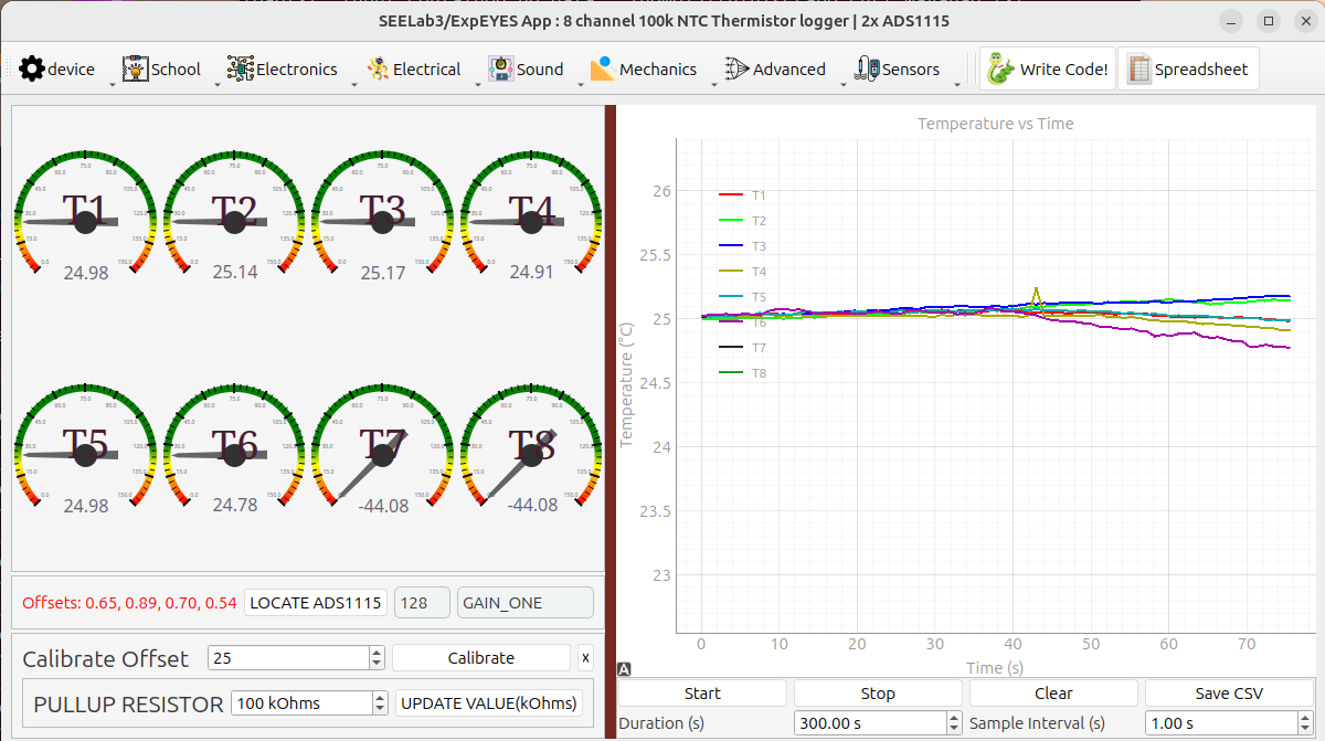
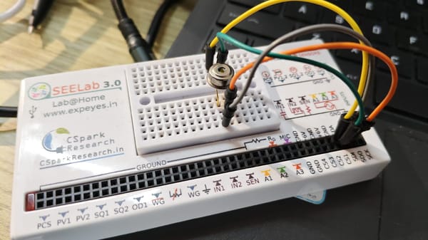
Fortunately, I have been able to identify a cheaply available device that puts the calibration process within the reach and capabilities of the end user. The ADS1115 16-bit ADC is a 4-channel, 0-3.3V ADC that can be interfaced via I2C. Typical initial accuracy of the internal voltage reference 0.01% and data rates higher than 500SPS are possible. The market is full of a clone IC with the module form cheaper than the TI IC, but those also perform quite well. It is cost effective, and is available in convenient module formats that can be directly plugged into SEELab
Basic requirements for the calibration process
The process to calibrate the analog inputs and outputs involves looping them externally , and monitoring the actual values via the external calibrator.
We’re killing two birds with one stone by calibrating inputs and outputs in tandem, and it makes for a faster calibration process. The complete calibration process for Digital to Analog converter outputs has enough complexity to warrant a separate post.
Let’s take an example; PV1 ( an analog output that can be set between -5V and +5V) can be connected to A1 (An analog input which can read voltage values between -16 and +16 Volts) with a small segment of wire, and various voltage values can be set on PV1, and read back by A1 . At the same time, the external calibration utility will also monitor this voltage, and store the error in PV1 (Set Voltage - Actual Voltage) as well as the error in A1 ( Read Voltage - Actual Voltage ) .
In a similar manner , PV2 can be connected to CH2, and the second channel of the ADS1115 calibrator can be used to monitor the real value, and so on .
I have incorporated a level shifting OP07 opamp to shift PV1 to the unipolar range in order to cross check it with the ADS1115.
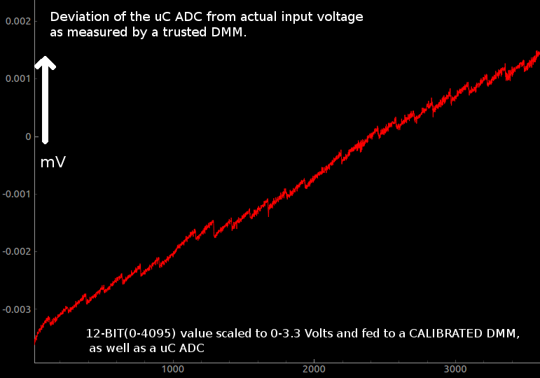
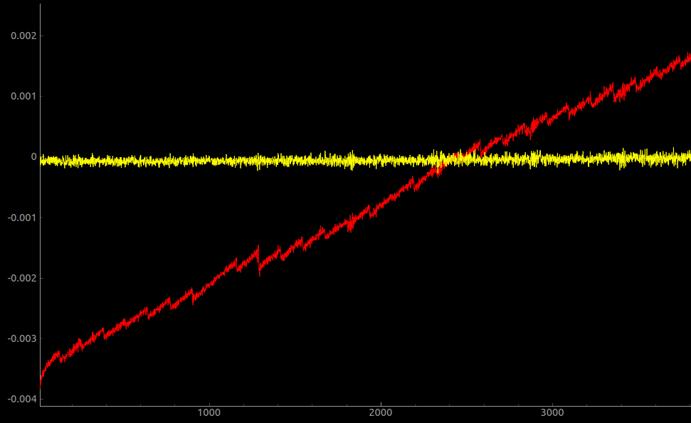
Integral Non-linearity of the ADC
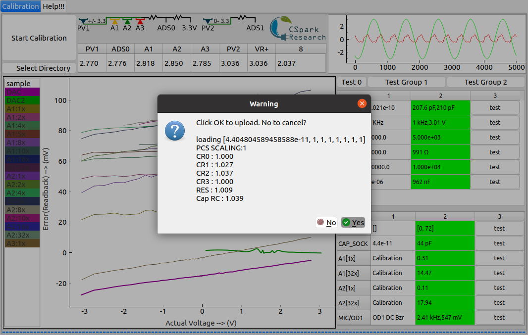
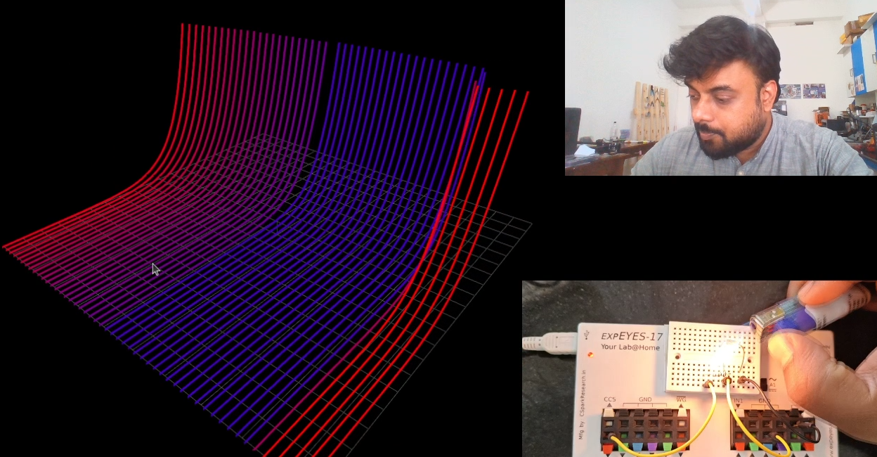
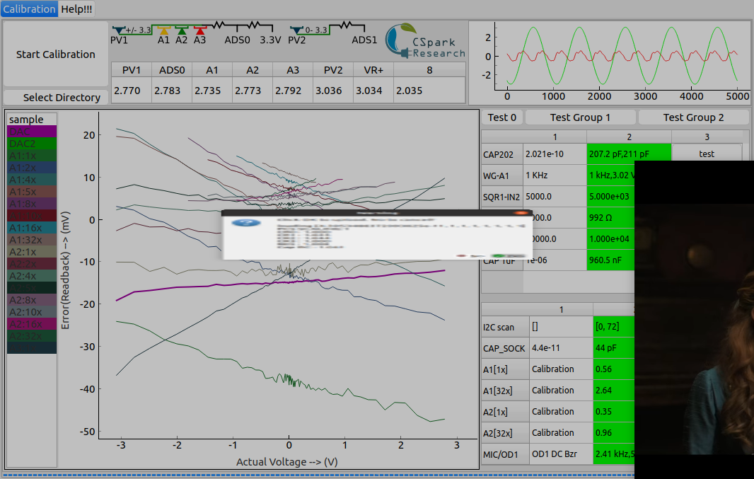
In addition to the overall slope and offset, if we consider a detailed error graph, a sawtooth pattern with an amplitude as small as the least count of the analog inputscan be seen superimposed on them. This error arises from the integral non-linearity (INL) of the analog to digital convertor of the PIC, and affects all analog inputs uniformly. While in principle we can ignore this for all practical purposes, in order to further improve the analog accuracy, we can also store this INL error of the ADC as a 2kb table, and apply this correction to any channel after its slope and offset has been corrected.
The following utilities and code are necessary for this process
- An I2C communication library for ADS1115 must be present in order to acquire data from it via SEELab
- The library should be able to handle the following tasks
- read single ended , and differential voltage values from any of the channels
- Enable selection of voltage range and voltage reference
- A graphical interface with the following features and algorithms will be required:
- Vary the output voltages from PV1,2 in small, definite intervals
- Store the errors in the analog outputs and inputs as a function of the actual voltage
- Generate Cubic interpolation functions for each input and output channel
- The Programmable Current Source can be calibrated using a measured Load resistor, and calibrated analog channel. Its interpolation function must also be stored.
- Write all calibration constants into flash memory after assigning a timestamp
- Store raw calibration data in a client-side folder
- upload the data to my server so when you visit device->calibration in the SEELab3 app, you can view the calibration data and testing screenshot
Resources
- Integral Non-linearity error in ADCs: https://en.wikipedia.org/wiki/Integral_nonlinearity
- Understanding data convertors: http://www.ti.com/lit/an/slaa013/slaa013.pdf
- ADS1115 Datasheet : http://www.ti.com/lit/ds/symlink/ads1114.pdf
- ADC and DAC Non-Linearity
Tags: ADC, DAC, ADS1115, 16-bit ADC , Calibration, Testing, Op-amps, Analog, Flash, SEELab, ExpEYES