Measuring Rotational Speed with the Stroboscopic Effect using SEELab 3.0

Have you ever noticed helicopter blades or car wheels appearing to rotate backward—or stay completely still—on camera or under flickering streetlights? This fascinating visual phenomenon is known as the Stroboscopic Effect.
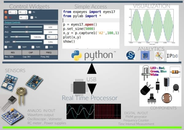
Using SEELab 3.0 (or ExpEYES hardware), you can easily demonstrate this optical illusion in the lab and turn it into a non-contact tachometer(rotational speed sensor) to measure the angular velocity of a motor.
1. What is the Stroboscopic Effect?
The stroboscopic effect occurs when a moving object is illuminated by a series of short, periodic light flashes rather than continuous light.
If an object completes an exact number of rotations between consecutive light pulses, it will be illuminated at precisely the same angular position every time. Because the human eye retains images for roughly $\frac{1}{16}^{th}$ of a second (persistence of vision), our brain perceives the object as completely stationary! In the video and header image you can see the letter R pasted on the spinning motor appear to come to a standstill even though it's spinning.
2. Circuit Wiring & Hardware Setup
To perform this experiment, you will need a small DC motor (such as a 3V DVD motor), a bright white LED, and your SEELab 3.0 unit.
Component | SEELab 3.0 Connection | Purpose |
|---|---|---|
DVD Motor (+) | PV1 | Programmable Voltage output (controls motor speed) |
DVD Motor (-) | GND | Ground reference |
LED Anode (+) | SQ1 | Square Wave Output (32-bit PWM generator) |
LED Cathode (-) | GND | Ground reference |
Preparation Tip: Draw a distinct white dot or line on the dark pulley of the motor spindle using a marker or correction pen so its orientation is clearly visible under illumination. In the video I have pasted the letter R on the spindle.
3. Step-by-Step Experimental Procedure
- Power the Motor: Open the SEELab 3.0 software and set the programmable voltage output PV1 to 1.0 V (or up to 2.0 V). The motor will begin spinning smoothly.
- Enable the Light Pulse: Turn on the square wave generator SQ1. Set the duty cycle to a small value (e.g., 5% to 10%) so the LED emits sharp, short bursts of light rather than remaining lit continuously.
- Coarse Tuning: Gradually increase or decrease the frequency of SQ1 in the GUI while looking directly at the illuminated motor pulley.
- Fine Tuning: As$f_{\text{flash}}$ approaches $f_{\text{motor}}$, the rotating mark will slow down. Fine-tune the frequency step-by-step until the dot comes to a complete standstill.
- Record & Verify:
- Record the frequency $f_{\text{flash}}$ from SQ1. This equals $f_{\text{motor}}$.
- Multiply by 60 to convert to RPM (Revolutions Per Minute) if you want:$$\text{RPM} = f_{\text{motor}} \times 60$$
- Double the frequency ($2 \cdot f_{\text{flash}}$) to observe two static dots, confirming that it's the fundamental frequency measurement.
4. Real-World Applications
The stroboscopic technique is widely used in science and engineering:
- Industrial Tachometry: Measuring rotational speeds of high-speed turbines and engines without attaching mechanical sensors that could add load or friction.
- Vibration Analysis: Inspecting stress fractures in operating machinery or vibrating strings in real time.
- Stop-Motion Photography: Capturing ultra-fast physical events, such as water droplets or ballistic impacts.
- Try to use this to find the speed of a ceiling fan
- You can also try to freeze the motion of a guitar string by providing a matching illumination frequency
5. Theoretical Background & Mathematical Physics
Let:
- $f_{\text{motor}}$be the actual rotational frequency of the motor (in Hz or revolutions per second).
- $f_{\text{flash}}$be the frequency of the flashing LED (in Hz).
- $\omega$be the angular velocity of the motor in radians per second:$$\omega = 2\pi f_{\text{motor}}$$
A. The Stationary Condition
The motor spindle appears completely frozen when the illumination frequency equals the rotational frequency:
$$f_{\text{flash}} = f_{\text{motor}}$$
It also appears stationary at sub-harmonics ($n = 2, 3, 4, \dots$):
$$f_{\text{flash}} = \frac{f_{\text{motor}}}{n}$$
(Note: At higher harmonic frequencies where$f_{\text{flash}} = n \cdot f_{\text{motor}}$, you will see$n$static images of the dot distributed evenly around the pulley circle).
B. Apparent Rotation (Beat Frequencies)
When the flashing frequency is slightly offset from the motor speed, the object appears to rotate slowly. The apparent frequency$f_{\text{apparent}}$is given by:
$$f_{\text{apparent}} = \vert{}f_{\text{motor}} - f_{\text{flash}}\vert{}$$
- If$f_{\text{flash}} < f_{\text{motor}}$, the pattern appears to crawl forward.
- If$f_{\text{flash}} > f_{\text{motor}}$, the pattern appears to crawl backward.
So , in summary
By pairing SEELab 3.0's programmable DC voltage output (PV1) with its high-resolution 32-bit PWM output (SQ1), you can build a precise, non-contact optical tachometer right on your workbench!