Scientific instruments as state machines: A case study, SEELab 3.0

The SEELab 3 hardware

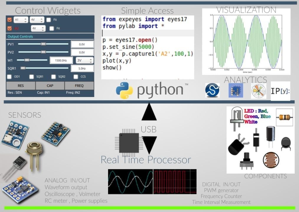
SEELab is a USB powered, multi-purpose data acquisition and control instrument that can be used to automate various test and measurement tasks via its companion android app, or desktop software. It is primarily intended for use in Physics and electronics laboratories in order to enable students to perform more advanced experiments by leveraging the powerful analytical and visualization tools that its frontend software and android app include.
Real time measurement instruments require specialized analog signal processors, and dedicated digital circuitry that can handle time critical tasks without glitches. SEELab3.0 has a 64MHz processor which runs a dedicated state machine that accepts commands sent by the host software, and responds according to a predefined set of rules.
It does not deviate from this fixed workflow, and therefore can very reliably measure time intervals at the microsecond length scales, or output precise voltage pulses.
In contrast, a GHz range desktop CPU running an OS is not capable of such time critical tasks under normal conditions because a multitude of tasks/programs are being simultaneously handled by the scheduler, and delays of the order of milliseconds might occur between one instruction and the next in a given piece of software. The hardware combines the flexibility and reliability of its dedicated processor, and the high computational and visualization abilities of the host computer/phone’s processor to create a very advanced, high-end product.
An outline of how the state machine(Feature Image) works
But first, you might be interested in the complete set of features of this instrument, and maybe screenshots from a few experiments . Here’s the web page for the device
From the flow diagram, it is apparent that the Hardware communicates to the host PC via a bidirectional communication channel, carries out instructions, and might even communicate to a secondary client via additional communication channels.
The default state of the hardware is to listen to the host. The host usually sends a 2- byte header first, the first byte is a broad category classifier, and the second refers to a specific command. Once the header is received , SEELab either starts executing the task , or listens for further data that may contain configuration parameters
An example for configuring the state of the digital outputs [These values are stored in header files common to the host as well as the hardware:
Bytes sent by the host :
- Byte #1 : 8 #DOUT
- Byte #2 : 1 #SET_STATE
- Byte #3 : One byte representing the outputs to be modified, and the nature of the modification (HIGH / LOW ). Four MSB bits contain information regarding the digital outputs SQ1,SQ2,OD1,CS1-4 that need to be toggled, and four LSBs contain information regarding the state that each selected output needs to be set to.
Action taken by the hardware:
- Move to the set_state routine
- Set the output state of the relevant output pins if required.
- Respond with an acknowledgement
- Move back to listening state
Bytes Returned by the hardware:
- Byte #1 : 254 ACKNOWLEDGE. SUCCESSFUL.
In a similar manner, instruments ranging from oscilloscopes, frequency counters, capacitance meters, data buses etc are all handled.
For function calls that are time consuming, the communication process might be split into separate exchanges for initialization, and data download. One such example is the Oscilloscope capture routine. The first information exchange sets the parameters for data acquisition, and the second occurs when the acquisition process is complete.
Host-Side Scripts and Software
The software running on the host runs either a dedicated script that sequentially acquires data or executes control tasks , or it runs an event loop where user inputs are used to determine the acquisition task to be executed.
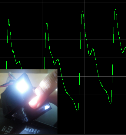
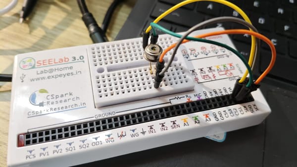
A phototransistor is connected to the SEN input of SEELab, and the host software reads the voltage on SEN at fixed intervals.
The conductance of the phototransistor fluctuates along with the incident light intensity, and this is translated into a voltage value by the internal signal processor of the SEN input.
When the photosensor is covered with a finger, and a bright light is passed through the finger, a time linked plot of these voltage fluctuations reflects the fluctuations in blood pressure, and therefore has the same frequency of the heart beat of the owner of this finger.
* The digital output OD1 is used to power a white LED being used as the light source here
Bibliography:
[1]: My Journey through the development of many such devices
[2] : Original content developed for the SEELablet’s first revision, from which ExpEYES-17, SEELab are derived. https://csparkresearch.in/seelablet/seelablet.html
[3]: Bulk Manufacturing Video and blog for KuttyPy. SEELab is assembled at the same facility. https://csparkresearch.in/manufacturing/pick-and-place.html